They used to say that robots would take over the jobs too dirty or dangerous for humans. That is exactly what [Joel Sullivan] had in mind when he created this welding robot. [Joel] designed the robot for the OSB industry. No, that’s not a new operating system, it’s short for Oriented Strand Board. An engineered lumber, OSB is made of strands (or chips) of wood. It’s similar to plywood but doesn’t require large thin sheets of lumber. To make a panel of OSB, a 5-inch thick matt of wood chips is mixed with glue and compressed down to 5/16″ at 7500 PSI and 400° F.
The presses used to make OSB are a massively parallel operation. 20 or more boards can be pressed at once. Thy press is also a prime area for damage. A nut or bolt hidden in the wood will dig into the press, causing a dent which will show up on every sheet which passes through that section. The only way to fix the press is to shut it down, partially dismantle it, and fill the void in with a welder. [Joel’s] robot eliminates most of the downtime by performing the welding on a still hot, still assembled press.
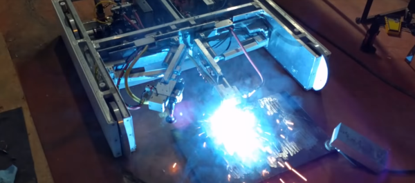
The robot looks like it was inspired by BattleBots, which is fitting as the environment it works in is more like a battleground. It’s a low, wide machine. In the front are two articulated arms, one with a welder, and one with a die grinder. The welder fills any voids in the press platen, and the die grinder grinds the fresh welds flat. An intel NUC controls things, with plenty of motor drives, power supplies, and relays on board.
[Joel’s] bot is tethered, with umbilicals for argon, electricity and compressed air. Air travels through channels throughout the chassis and keeps the robot cool on the hot press. Everything is designed for high temperatures, even the wheels. [Joel] tried several types of rubber, but eventually settled on solid aluminum wheels. The ‘bot doesn’t move very fast, so there is plenty of traction. Some tiny stepper motors drive the wheels. When it’s time to weld, pneumatic outriggers lock the robot in place inside the narrow press.
Cameras with digital crosshairs allow the operator to control everything through a web interface. Once all the parameters are set up, the operator clicks go and sparks fly as the robot begins welding.
If you’re into seriously strong robots, check out trackbot, or this remote-controlled snow blower!
Continue reading “Welding Robot Takes On A Hot, Dirty, Dangerous Job”


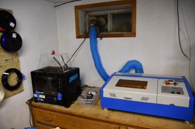 Over the last decade or so things have changed. China got involved, and suddenly there were cheap lasers on the market. Currently, there are several low-cost laser models available in various power levels. The most popular is the smallest – a 40-watt model, dubbed the K40. There are numerous manufacturers and there have been many versions over the years. They all look about the same though: A blue sheet metal box with the laser tube mounted along the back. The cutting compartment is on the left and the electronics are on the right. Earlier versions came with Moshidraw software and a parallel interface.