You only really need two data wires to transfer a ton of data. Standards like UART, USB2, I2C, SPI, PS/2, CAN, RS232, SWD (an interface to program MCUs), RS485, DMX, and many others, all are a testament to that. In particular, I2C is such a powerful standard, it’s nigh omnipresent – if you were to somehow develop an allergy to I2C, you would die.
Chances are, whatever device you’re using right now, there’s multiple I2C buses actively involved in you reading this article. Your phone’s touchscreen is likely to use I2C, so is your laptop touchpad, most display standards use I2C, and power management chips are connected over I2C more often than not, so you’re covered even if you’re reading this on a Raspberry Pi! Basically everything “smart” has an I2C port, and if it doesn’t, you can likely imitate it with just two GPIOs.
If you’re building a cool board with a MCU, you should likely plan for having an I2C interface exposed. With it, you can add an LCD screen with a respectable resolution or a LED matrix, or a GPS module, a full-sized keyboard or a touchpad, a gesture sensor, or a 9 degree of freedom IMU – Inertial Measurement Unit, like a accelerometer+compass+gyroscope combination. A small I2C chip can help you get more GPIOs for your MCU or CPU, or a multi-channel motor driver, or a thermal camera, or a heap of flash memory; if you’re adding some sort of cool chip onto your board, it likely has an I2C interface to let you fine-tune its fancy bits.
As usual, you might have heard of I2C, and we sure keep talking about it on Hackaday! There’s a good few long-form articles about it too, both general summaries and cool tech highlights; this article is here to fill into some gaps and make implicit knowledge explicit, making sure you’re not missing out on everything that I2C offers and requires you to know!


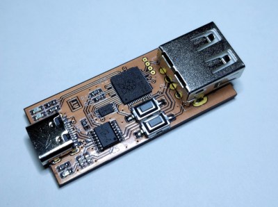 [ataradov] also offers us a complete board design with a RP2040 and a USB hub on it, equipped with USB sockets that completely free us from the soldering requirement; it’s


