Color Changing EL Wire

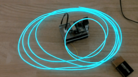
All EL wire drivers use a resonator circuit to supply power to the EL wire. It’s an efficient system, but [Paul] noticed that there was some color change when powering different lengths of wire off of the same driver. He realized that this is because of the changing frequency of the resonator circuit, so the only reasonable thing for [Paul] to do was to build a color fading EL wire driver.

The circuit used to drive the wire is very simple. [Paul] used a Teensy board to switch two transistors and produce AC current. This is sent through a step-up transformer which powers the EL wire. It was necessary to use aqua or ‘Tron blue’ EL wire for this build because of the clear wire jacket. Many colors of EL wire have a fluorescent jacket – much like a fluorescent light bulb – that changes the color produced inside the wire to something different. [Paul] says the color change is subtle, but unique.

Of course the build is nothing without a video of the color changing EL wire. Check it out after the break.

Continue reading “Color Changing EL Wire”

Building A Solar Power Heliostat

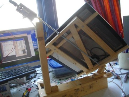
[Frits] has been working on an solar panel heliostat (in Dutch, check out the translated page here).

The heliostat uses a small PICAXE to control the motor, along with an DS1307 real-time clock to make sure the motors start at dawn. Instead of using optical encoders or magnetic sensors, the angle of the heliostat is measure with a pot attached to the drive shaft. [Frits] did a lot of data collection to figure out that this method is accurate to about 1 degree – just fine for something that doesn’t need to be exact.

According to [Frits] this heliostat will put out 12 to 50 percent more electricity than a fixed panel. Although the build does seem a little bulky, putting it on a  house with a roof pitch of 23.5° would greatly reduce the horizontal profile.

A video of a solar panel rotating at 15 degrees/hour isn’t that interesting, so [Frits] posted a clip of 6 mirrors slewing around fairly fast to demonstrate his system. Check it out after the break.

Continue reading “Building A Solar Power Heliostat”

Zzstructure Emulator

[John Ohno] has been working on a zzstructure operating system written C since January. [John] realizes not many people know what a zzstructure is, so he posted a demo of his project. [John] has also put all the code online.

A zzstructure is both a hypertext and operating system unlike anything we have today. You could say that when it was first conceived in 1960 it was 100 years ahead of its time. [John]’s implementation of zzstructures operates on a 256-dimension grid and functions a lot like a multidimensional forum thread. Although that’s a lot to wrap your head around, it can probably best be explained by [Ted Nelson], the creator of zzstructures.

Continue reading “Zzstructure Emulator”

Wearable Video Coat

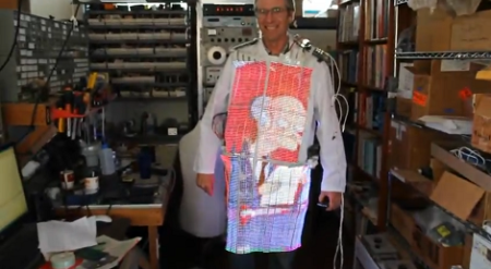
[David Forbes] is no stranger to the weird and esoteric, so he created a color LED TV built into a lab coat. He plans on bringing it to Burning Man next month.

The RGB LEDs are mounted narrow flex boards, providing a 160×120 pixel NTSC display. Video processing is taken care of by an Xilinx FPGA that takes the YCrCb video feed from a video iPod and converts it into four separate RGB streams for the front, back, and the two sides. The requisite controls for brightness and color are on the shoulders.

Of course, the build wouldn’t be over-the-top without the ability to plug a Nintendo into a lab coat, so there’s an NTSC input on an RCA jack. Everything is powered by two 11.1 V, 5Ah radio-control LiPo battery packs that should power this for a while.

Check out a video of the LED lab coat below.

[youtube=http://www.youtube.com/watch?v=jtSm8Oom2n4&w=470]

LED Wand For Light Painting Photography

[Michael Ross] is a photographer who has been getting into light painting recently. He’s come up with his own RGB light wand to create some amazing images, and also written a very, very thorough tutorial (PDF warning) on how to build your own light wand.

The light wand is based on an Arduino Mega board and uses an RGB LED strip based on the HL1606 controller chip. We’ve covered these LED strips before, and they’re very easy to use with the requisite library. So far, [Michael] has built a 48-LED light wand and a 16-LED wand with a 6-position program selector, making it easy to do awesome single-exposure photos like this.

[Michael] creates his images in an Excel spreadsheet – rows are which LED to address and columns are units of time. The picture data is then copied and pasted straight from the Excel worksheet to the Arduino source code. This in itself is a pretty clever use of Excel.

Check out the how [Michael] creates one of his light paintings here.

Sound Card Microcontroller/PC Communication

The usual way send data from a microcontroller is either over RS-232 with MAX232 serial ICs, crystals, and a relatively ancient computer, or by bit-banging the USB protocol and worrying about driver issues. Not content with these solutions, [Scott] came up with sound card μC/PC communication that doesn’t require any extra components.

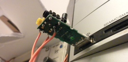
[Scott] bought a cheap USB sound card dongle on eBay (although a built-in sound card will do) and wired up the tip and ring of the plug to the microcontroller. The data is sent from the microcontroller a lot like Morse code – a short gap between pulses is a zero, a long gap is a one. This is parsed by a Python script using PyAudio. Synchronization, timing, and calibration is automatic because of a 10-bit ‘packet header’ explained in this video.

Continue reading “Sound Card Microcontroller/PC Communication”

Improved FPGA Synth

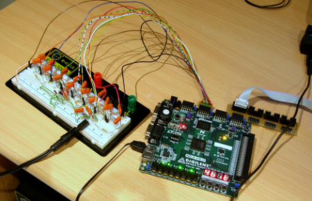
A week or so ago we featured an FPGA MIDI interface. Since then the builder has gone crazy with his FPGA and revised his code to include polyphony and PWM output, and posted a polyphony demo.

In our previous coverage of the build, the synth was monophonic, and the MIDI implementation was pretty shaky. After realizing the hard work was done, [Mich] re-wrote the MIDI interpretation module to keep 8 voices in memory. Now the synth can play 16th note arpeggios at 999bpm.

The original build used 8 pins to output the audio with an R/2R ladder for a digital to analog converter. This didn’t work well with a polyphonic synth (everything was clipped or noisy), so [Mich] moved to PWM output.

Continue reading “Improved FPGA Synth”