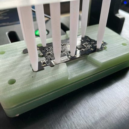
Prolific maker [Jan Mrázek] shared his process for casting soft silicone parts that nevertheless have some added stiffness, which he accomplished by embedding porous, 3D-printed “ribs” into the pieces during the casting process. The 3D-printed inserts act as a sort of skeleton, and as a result, the parts have a soft silicone surface but gain structure and rigidity that simply wouldn’t be obtained if the part were cast entirely in silicone. The nice thing is that no new materials or tools were needed; [Jan] 3D printed both the molds for the parts as well as the structural inserts. It’s always nice when one can use the same tool and materials to accomplish different functions.
 The parts [Jan] is making are interesting, as well. He observed that the process of swapping resin in his printer’s build tank was an unpleasant experience for a number of reasons, chief among them being that resin is sticky and messy, and the shape of the build tank doesn’t make pouring resin from it a clean job.
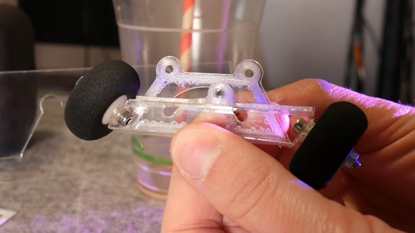
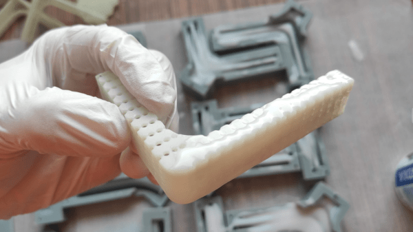
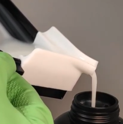
His solution was to design a pour spout that could be pressed onto the build tank, and some specially-designed squeegees to allow scraping the tank clean with ease. Silicone is the ideal material for the parts because it turns out that sticky resin beads nicely on silicone’s surface. Anywhere else, resin tends to spread out and form a sticky mess, but on silicone resin it forms tidy drops and is much easier to clean up.
It’s a technique worth keeping in mind, because one never knows when it could come in handy. Fabricating soft robots for example tends to involve silicone casting and clever techniques. See [Jan]’s parts in action in the video, embedded below.
Continue reading “Casting Silicone Parts With 3D-Printed Inserts For Stiffness”