Improved Flexible Build Plate For SLA Is Ready To Rock

The Elegoo Mars is an affordable SLA (resin-based) 3D printer, and there are probably few that have seen more mods and experimentation than [Jan Mrázek]’s machine. The final design of his DIY flexible build plate is a refinement of his original proof of concept, which proved a flexible build platform can be every bit as useful on an SLA printer as it is for FDM; instead of chiseling parts off a rigid build platform, simply pop the flexible steel sheet off the magnetic base and flex it slightly for a much easier part removal process. His original design worked, but had a few rough edges that have since been ironed out.

[Jan]’s magnetic build platform.
We love how [Jan] walks through all of the design elements and explains what worked and what didn’t. For example, originally he used a galvanized steel sheet which was easy enough to work with, but ended up not being a viable choice because once it’s bent, it stays bent. Spring steel is a much better material for a flexible build platform, but is harder for a hobbyist to cut.

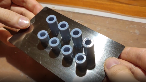
Fortunately, it’s a simple job for any metal fabrication shop and [Jan] got a variety of thicknesses cut very cheaply. It turns out that the sweet spot is 0.3 mm (although 0.2 mm is a better choice for particularly fragile parts.) [Jan] also suggests cutting the sheet a few millimeters larger than the build platform; it’s much easier to peel the sheet off the magnetic base when one can get a fingertip under an edge, after all.

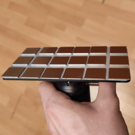
The magnetic base that the steel sheet sticks to is very simple: [Jan] converted a stock build platform by mounting an array of 20 x 20 x 1 mm magnets with 3M adhesive mounting tape. He was worried that resin might seep in between the magnets and cause a problem, perhaps even interfering with the adhesive; but so far it seems to be working very well. Resin is viscous enough that it never penetrates far into the gaps, and no effect on the adhesive has been observed so far.

Watch how easily parts are removed in the short video embedded below, in which [Jan] demonstrates his latest platform design.

Continue reading “Improved Flexible Build Plate For SLA Is Ready To Rock”

Complex Wood Joints, Thanks To New Software’s Interactive Features

Artfully-crafted wooden joints that fit together like puzzle pieces and need neither glue nor nails is fascinating stuff, but to call the process of designing and manufacturing them by hand “time-consuming” would be an understatement. To change that, a research team from the University of Tokyo presented Tsugite, a software system for interactively designing and fabricating complex wooden joints. It’s named after the Japanese word for joinery, and aims to make the design and manufacture of glue and fastener-free joints much easier than it otherwise would be.

Three-way joint that requires no glue or fasteners.

It looks like the software is so far only a research project and not something that can be downloaded The software is available on GitHub and the approach it takes is interesting. This downloadable PDF explains how the software deals with the problem of how to make such a task interactive and practical.

The clever bit is that the software not only provides design assistance for the joints themselves in a WYSIWYG (what you see is what you get) interface, but also generates real-time feedback based on using a three-axis CNC tool as the manufacturing method. This means that the system understands the constraints that come from the fabrication method, and incorporates that into design feedback.

The two main limitations of using a three-axis CNC are that the cutting tool can only approach the material from above, and that standard milling bits cannot create sharp inner corners; they will have a rounded fillet the same radius as the cutting bit. Design can be done manually, or by selecting joints from a pre-defined gallery. Once the design is complete, the system generates the toolpaths for manufacture.

Currently, Tsugite is limited to single joints meant for frame structures, but there’s no reason it couldn’t expand beyond that scope. A video to accompany the paper is embedded below, it’s short and concise and shows the software in action, so be sure to give it a look.

Continue reading “Complex Wood Joints, Thanks To New Software’s Interactive Features”

Pulse Oximetry Sensor Judges Your Coffee Roast

Breakout board for the MAX30101, which [Zach] used as the basis of his roast gauge. The sensor is at the top edge of the board.
Parts designed and marketed for a specific application can nevertheless still be useful in other ways, and whenever that happens, it’s probably the start of a pretty good hack. Using a sensor for something other than its intended purpose is exactly what [Zach Halvorson] did to make the Roast Vision device, which uses the MAX30101, a sealed optical sensor intended mainly for pulse oximetry and heart-rate monitoring.

[Zach] is instead using that sensor to measure the roast level of coffee beans, and assign a consistent number from 0 to 35 to represent everything from Very Dark to Very Light. Measuring a bean’s roast level is important to any roaster seeking accuracy and consistency, but when [Zach] found that commercial roast gauges could easily cost over a thousand dollars, he was sure he could do better.

[Zach] settled on using a Sparkfun MAX30101 breakout board to develop his device, and Sparkfun shared an informative blog post that demonstrates how making hardware and tools more accessible can help innovative ideas flourish. The Roast Vision device has a 3D printed enclosure, and a simple top-loading design with an integrated sample cup makes it easy to use. One simply puts about a teaspoon of finely-ground coffee into the sample cup, and the unit provides a measurement in a couple of seconds. Fortunately the sensor works just fine though an acrylic window which means the device can be sealed; a handy feature for a tool that will spend a lot of time around ground coffee.

The joys of fresh roasted coffee is something that is perfectly accessible to those making small batches at home. There are commercial options for small roasters of course, but should you wish to go the DIY route, check out our own Elliot Williams’ guide on making a low-cost DIY roaster.

Light Fields: Missing Ingredient For Immersive 3D Video Gets Improved

46 time-synchronized action cameras make up the guts of the capture device.

3D video content has a significant limitation, one that is not trivial to solve. Video captured by a camera — even one with high resolution and a very wide field of view — still records a scene as a flat plane, from a fixed point of view. The limitation this brings will be familiar to anyone who has watched a 3D video (or “360 video”) in VR and moved their head the wrong way. In these videos one is free to look around, but may not change the position of their head in the process. Put another way, pivoting one’s head to look up, down, left, or right is fine. Moving one’s head higher, lower, closer, further, or to the side? None of that works. Natural movements like trying to peek over an object, or moving slightly to the side for a better view simply do not work.

Light field video changes that. It is captured using a device like the one in the image above, and Google has a resource page giving an excellent overview of what light field video is, what it can look like, and how they are doing it. That link covers recent improvements to their camera apparatus as well as to video encoding and rendering, but serves as a great show-and-tell of what light fields are and what they can do.

Continue reading “Light Fields: Missing Ingredient For Immersive 3D Video Gets Improved”

Adding Crush Ribs To 3D Printed Parts For A Better Press Fit

[Dan Royer] shared a tip about how to get a reliably tight fit between 3D printed parts and other hardware (like bearings, for example.) He suggests using crush ribs, a tried-and-true solution borrowed from the world of injection molding and repurposed with 3D printing in mind. Before we explain the solution, let’s first look at the problem a little more closely.

Imagine one wishes to press-fit a bearing into a hole. If that hole isn’t just the right size, the bearing won’t be held snugly. If the hole is a little too big, the bearing is loose. Too small, and the bearing won’t fit at all. Since a 0.1 mm difference can have a noticeable effect on how loose or snug a fit is, it’s important to get it right.

Crush rib locations highlighted with blue arrows.

For a 3D printed object, a hole designed with a diameter of 20 mm (for example) will come out slightly different when printed. The usual way around this is to adjust printer settings or modify the object until the magic combination that yields exactly the right outcome is found, also known as the Goldilocks approach. However, this means the 3D model only comes out right on a specific printer, which is a problem for a design that is meant to be shared. Since [Dan] works on robots with 3D printed elements, finding a solution to this problem was particularly important.

The solution he borrowed from the world of injection molding is to use crush ribs, which can be thought of as a set of very small standoffs that deform as a part is press-fit into them. Instead of a piece of hardware making contact with the entire inside surface of a hole, it makes contact only with the crush ribs. Press fitting a part into crush ribs is far easier (and more forgiving) than trying to get the entire mating surface exactly right.

Using crush ribs in this way is a bit of a hack since their original purpose in injection molding is somewhat different. Walls in injection-molded parts are rarely truly flat, because that makes them harder to eject from a mold. Surfaces therefore have a slight cant to them, which is called a draft. This slight angle means that press fitting parts becomes a problem, because any injection-molded hole will have slanted sides. The solution is crush ribs, which — unlike the walls — are modeled straight. The ribs are small enough that they don’t have an issue with sticking in the mold, and provide the mating surface that a press-fit piece of hardware requires. [Dan] has a short video about applying this technique to 3D printed objects, embedded below.

Continue reading “Adding Crush Ribs To 3D Printed Parts For A Better Press Fit”

Art of 3D printer in the middle of printing a Hackaday Jolly Wrencher logo

3D Printering: Wash Parts Better And Make Solvent Last Longer

SLA printing in resin is great, but part washing can be a hassle. The best results come from a two-stage wash, but that also means more material and more processing steps. Fortunately, there are ways to make it easier and more effective. One such way is to use a part washing machine, and I’ll cover a DIY option to make your own, but despite what the advertising implies for the commercial ones, a wash machine isn’t a cure-all.

Let’s go through how to get the best results from part washing, how to make the solvent last as long as possible, and how to dispose of the eventual waste.

Resin-Printed Parts Need Washing

All parts printed in resin emerge from the printer coated in syrupy, uncured goop. This needs to be removed completely, or the print ends up sticky and no amount of drying or additional UV curing will change that. (There is a way to fix sticky prints, but it’s better to avoid the situation in the first place.)

Simple part washing can be done with nothing more than a jar in which to rinse and soak a small part for about ten minutes, but agitation and a secondary wash will go a long way toward better and more consistent results. As mentioned, part washing machines like to present themselves as a one-appliance solution, but best results still come from a two-stage wash, and that means some additional steps.

Continue reading “3D Printering: Wash Parts Better And Make Solvent Last Longer”

Spare SMD Storage, With Stacking SMT Tape Reels

[Kadah]’s solution for storing short tapes of SMT parts is as attractive as it is clever. The small 3D-printed “tape reels” can double as dispensers, and stack nicely onto each other thanks to the sockets for magnets. The units come in a few different sizes, but are designed to stack in a consistent way.

We love the little touches such as recessed areas for labels, and the fact that the parts can print without supports (there are a couple of unsupported bridges, but they should work out fine.) Also, the outer dimensions of the units are not an accident. They have been specifically chosen to nestle snugly into the kind of part drawers that are a nearly ubiquitous feature of every hardware hacker’s work bench.

STLs are provided for handy download but [Kadah] also provides the original Fusion 360 design file, with all sizes defined as easily-customized parameters. In addition, [Kadah] thoughtfully provided each model in STEP format as well, making it easy to import and modify in almost any 3D CAD program.

Providing 3D models in STEP format alongside STLs is nice to see, because it gives more options to people if things need some tweaking, because editing the STL file can be done if needed, but isn’t optimal. Thankfully the ability to export STEP files is still open to hobbyists using Fusion 360, since Autodesk decided to leave that feature available to personal use licenses.