Scramblepad Teardown Reveals Complicated, Expensive Innards

What’s a Scramblepad? It’s a type of number pad in which the numbers aren’t in fixed locations, and can only be seen from a narrow viewing angle. Every time the pad is activated, the buttons have different numbers. That way, a constant numerical code isn’t telegraphed by either button wear, or finger positions when punching it in. [Glen Akins] got his hands on one last year and figured out how to interface to it, and shared loads of nice photos and details about just how complicated this device was on the inside.

Just one of the many layers inside the Scramblepad.

Patented in 1982 and used for access control, a Scramblepad aimed to avoid the risk of someone inferring a code by watching a user punch it in, while also preventing information leakage via wear and tear on the keys themselves. They were designed to solve some specific issues, but as [Glen] points out, there are many good reasons they aren’t used today. Not only is their accessibility poor (they only worked at a certain height and viewing angle, and aren’t accessible to sight-impaired folks) but on top of that they are complex, expensive, and not vandal-proof.

[Glen]’s Scramblepad might be obsolete, but with its black build, sharp lines, and red LED 7-segment displays it has an undeniable style. It also includes an RFID reader, allowing it to act as a kind of two-factor access control.

On the inside, the reader is a hefty piece of hardware with multiple layers of PCBs and antennas. Despite all the electronics crammed into the Scramblepad, all by itself it doesn’t do much. A central controller is what actually controls door access, and the pad communicates to this board via an unencrypted, proprietary protocol. [Glen] went through the work of decoding this, and designed a simplified board that he plans to use for his own door access controller.

In the meantime, it’s a great peek inside a neat piece of hardware. You can see [Glen]’s Scramblepad in action in the short video embedded below.

Continue reading “Scramblepad Teardown Reveals Complicated, Expensive Innards”

Power Up Vintage Electronics Less Unsafely With A Dim-Bulb Tester

Plugging in something like an antique radio to see if it works is a good way to have a bad time, because some old components don’t age well. For vintage electronics, inspection and repair are steps one and two. When it comes time to cautiously apply power, it’s best to use what’s called a dim-bulb tester and most hackers can probably put one together from scrap.

Being able to use one (or both) bulbs adds some flexibility, and the embedded power monitor is an inexpensive and handy addition.

These testers make it easier, and safer, to tell if there are any big problems with a device’s power supply. In its simplest form, a dim-bulb tester puts an incandescent lamp in series between a device — like an old radio — and the AC power from a wall socket. Thanks to this, if the device has a short circuit, the bulb will simply light up instead of causing any damage.

Ideally, one uses a bulb with a wattage rating that is roughly equal to the power consumption of the device being tested. If all is well, the bulb will glow very faintly and the device will work normally. A brightly glowing bulb would indicate excessive current draw. To allow some flexibility, [Doz]’s tester design allows using one or two 60 W incandescent bulbs in series, and even incorporates an inexpensive power monitor.

A dim-bulb tester isn’t an in-depth diagnostic tool but it is effective, simple, and allows for a safe startup even if there’s a serious problem like a short.  It helps protect valuable hardware from going up in smoke. In fact, the fundamental concept of limiting power to protect hardware in case of a fault has also been applied in the world of retrocomputing, where it helps protect otherwise irreplaceable hardware if something goes wrong.

RFID Sticker On Bike Helmet Grants Garage Access

[Glen] might describe his project of opening his garage door by way of an RFID sticker on his bike helmet as simple, but some of the interfacing he needed to do was quite complex. He walks through the project from beginning to end, and there’s plenty to learn from.

When designing an RFID access control system, one has to decide what kind of reader and what kind of tags one wishes to use. They all function more or less the same way, but there are a lot of practical considerations to take into account such as cost, range, ease of use, and security options. After a lot of research, [Glen] decided on inexpensive sticker-style tags and a compatible reader supporting credentials with an ISO14443 UID that could be suitably mounted on a building’s exterior.

The actual opening of the door was the simple part, done by interfacing to a spare remote.

Breakout boards with ready-to-use code libraries exist for some RFID readers, but that wasn’t the case for the reader [Glen] had. He ended up rolling his own code to handle communication with the reader, with a Microchip PIC18F45K50 doing all the work of reading tags and performing access control. His code is on the project’s GitHub repository, and if you also find yourself needing to interface to a reader that uses the Wiegand protocol, you might want to give it a look.

Controlling the actual garage door was the easy part. All that took was soldering two wires across the switch contacts of a spare garage door opener remote, and using a relay to close the contacts. Simple and effective. You can see it in action in the short video, embedded below the break.

Overhead door access control might be a simple concept, but it comes in all shapes and sizes when enterprising hackers start looking for solutions. We’ve seen garage doors given the DIY IoT treatment, and even seen access controlled by a car’s headlamp flashes, which actually turned out to be more secure than it sounds.

Continue reading “RFID Sticker On Bike Helmet Grants Garage Access”

Stop Silicone Cure Inhibition, No Fancy Or Expensive Products Required

Casting parts in silicone is great, and 3D printing in resin is fantastic for making clean shapes, so it’s natural for an enterprising hacker to want to put the two together: 3D print the mold, pour in the silicone, receive parts! But silicone’s curing process can be inhibited by impurities. What’s cure inhibition? It’s a gross mess as shown in the image above, that’s what it is. Sadly, SLA-printed resin molds are notorious for causing exactly that. What’s a hacker to do?

Firstly: there are tin-cure and platinum-cure silicones, and for the most part tin-cure silicone works just fine in resin-printed molds. Platinum-cure silicones have better properties, but are much more susceptible to cure inhibition. Most workarounds rely on adding some kind of barrier coating to molds, but [Jan Mrázek] has a cheap and scalable method of avoiding this issue that we haven’t seen before. Continue reading “Stop Silicone Cure Inhibition, No Fancy Or Expensive Products Required”

Garmin HUD Got Discontinued, But Not Trashed

The Garmin HUD+ was a small Bluetooth device intended for the dashboard of a car, meant to be used as a GPS heads-up display for data from Garmin smartphone apps. It used a bright VFD (vacuum fluorescent display) which was viewed through a clear reflector, and displayed GPS information and directions. It was discontinued in 2015, but [Doz] was fond of his and used it happily until a phone upgrade meant it no longer worked. Was it destined for a landfill? Not if he had anything to say about it!

The first thing [Doz] tried was using an alternate Android app, but since it also didn’t work, it was time to sit back and reflect on the scope of the issue. In [Doz]’s case, he really only wanted some basic meaningful data displayed, and decided he could do away with the phone altogether if he had the right hardware. Continue reading “Garmin HUD Got Discontinued, But Not Trashed”

ESP8266 Web Server Saves 60% Power With A 1 Ms Delay

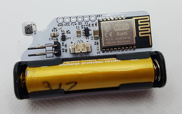
Arduino has a library for quickly and easily setting up a simple web server on an ESP8622-based board, and [Tomaž] found that power consumption on an ESP-01 can be reduced a considerable amount by simply inserting a 1 ms delay in the right place. The reason this works isn’t because of some strange bug or oddball feature — it’s really just a side effect of how the hardware operates under the hood.

[Tomaž] uses the “hello world” example from ESP8266WebServer to explain. In it, the main loop essentially consists of calling server.handleClient() forever. That process checks for incoming HTTP connections, handles them, sends responses, exits — and then does it all over again. A simple web server like this one spends most of its time waiting.

A far more efficient way to handle things would be to launch server.handleClient() only when an incoming network connection calls for it, and put the hardware to sleep whenever that is not happening. However, that level of control just isn’t possible in the context of the Arduino’s ESP8266WebServer library.

So what’s to be done? The next best thing turns out to be a simple delay(1) statement right after each server.handleClient() call in the main loop.

Why does this work? Adding delay(1) actually causes the CPU to spend the vast majority of its time in that one millisecond loop. And counting microseconds turns out to be a far less demanding task, power-wise, than checking for incoming network requests about a hundred thousand times per second. In [Tomaž]’s tests, that one millisecond delay reduced idle power consumption at 3.3 V from roughly 230 mW to around 70 mW — about 60% — while only delaying the web server’s response times by 6-8 milliseconds.

For simple web server applications, this is is for sure a good trick to keep in mind. There are also much more advanced techniques for saving power on ESP8266-based boards; from boards that barely sip a single microamp while sleeping, to coin-cell powered boards that go so far as to modify the TCP/IP stack to help squeeze every bit of power savings possible.

How The Image-Generating AI Of Stable Diffusion Works

[Jay Alammar] has put up an illustrated guide to how Stable Diffusion works, and the principles in it are perfectly applicable to understanding how similar systems like OpenAI’s Dall-E or Google’s Imagen work under the hood as well. These systems are probably best known for their amazing ability to turn text prompts (e.g. “paradise cosmic beach”) into a matching image. Sometimes. Well, usually, anyway.

‘System’ is an apt term, because Stable Diffusion (and similar systems) are actually made up of many separate components working together to make the magic happen. [Jay]’s illustrated guide really shines here, because it starts at a very high level with only three components (each with their own neural network) and drills down as needed to explain what’s going on at a deeper level, and how it fits into the whole.

Spot any similar shapes and contours between the image and the noise that preceded it? That’s because the image is a result of removing noise from a random visual mess, not building it up from scratch like a human artist would do.

It may surprise some to discover that the image creation part doesn’t work the way a human does. That is to say, it doesn’t begin with a blank canvas and build an image bit by bit from the ground up. It begins with a seed: a bunch of random noise. Noise gets subtracted in a series of steps that leave the result looking less like noise and more like an aesthetically pleasing and (ideally) coherent image. Combine that with the ability to guide noise removal in a way that favors conforming to a text prompt, and one has the bones of a text-to-image generator. There’s a lot more to it of course, and [Jay] goes into considerable detail for those who are interested.

If you’re unfamiliar with Stable Diffusion or image-creating AI in general, it’s one of those fields that is changing so fast that it sometimes feels impossible to keep up. Luckily, our own Matthew Carlson explains all about what it is, and why it matters.

Stable Diffusion can be run locally. There is a fantastic open-source web UI, so there’s no better time to get up to speed and start experimenting!