Get Ready For The Great Eclipse Of 2017

On August 21, 2017, the moon will cast its shadow across most of North America, with a narrow path of totality tracing from Oregon to South Carolina. Tens of millions of people will have a chance to see something that the continental US hasn’t seen in ages — a total eclipse of the sun. Will you be ready?

The last time a total solar eclipse visited a significantly populated section of the US was in March of 1970. I remember it well as a four-year-old standing on the sidewalk in front of my house, all worked up about space already in those heady days of the Apollo program, gazing through smoked glass as the moon blotted out the sun for a few minutes. Just watching it was exhilarating, and being able to see it again and capitalize on a lifetime of geekiness to heighten the experience, and to be able to share it with my wife and kids, is exciting beyond words. But I’ve only got eight months to lay my plans! Continue reading “Get Ready For The Great Eclipse Of 2017”

Old Motor Donates Rotor For Coaxial Wind Vane And Anemometer

Problem: build a combined anemometer and wind vane where the pivots for both sensors are coaxial. Solution: turn an old universal motor into a step-wise potentiometer for the wind vane, and then pull a few tricks to get the whole thing assembled.

commutatior-with-series-resistors
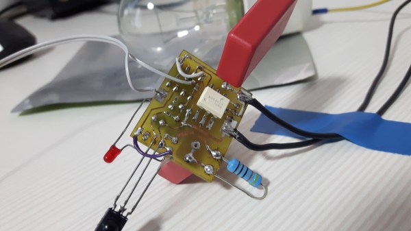
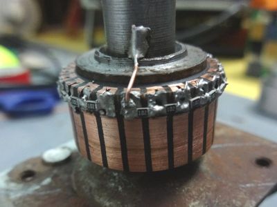
We have to admit that when we first saw [Ajoy Raman]’s Instructables post, we figured that he used a universal motor to generate a voltage from the anemometer. But [Ajoy]’s solution to the coaxial shafts problem is far more interesting than that. A discarded universal motor donated its rotor and bearings. The windings were stripped off the assembly leaving nothing but the commutator. 1kΩ SMD resistors were soldered across adjacent commutator sections to form a series resistance of 22kΩ with taps every 1k, allowing 0 to 2.2V to be read to the ADC of a microcontroller depending on the angle of the vane.

As clever as that is, [Ajoy] still had to pull off the coaxial part, which he did by drilling out the old motor shaft from one end to the other using just a drill press. The anemometer shaft passes through the hole in the shaft and turns a small DC motor to sense wind speed.

There might have been other ways to accomplish this, but given the constraints and the low cost of this solution, our hats are off to [Ajoy]. We’re a little concerned with that motor used for the anemometer, though. It could result in drag when used as a generator. Maybe a better solution would be a Hall-effect sensor to count rotations of a hard drive rotor.

Continue reading “Old Motor Donates Rotor For Coaxial Wind Vane And Anemometer”

Full-Auto Crossbow Rocks And Rolls On Rubber Bands And Electric Drill

You’ve got to enjoy any project where the hacker clearly loves what he or she is doing. And when the project is as cool as a motor-driven, rubber band powered, fully automatic crossbow, it’s hard not to laugh along.

A full-auto crossbow is no mean feat, and it took a man with a love for rubber-powered firearms to get it right. [JoergSprave]’s design is based on a rack-and-pinion system and executed mainly in plywood. The main pinion gear is a composite of aluminum and wood, in a bid to increase the life of the mechanism and to properly deal with the forces involved. The pinion, turned by a powerful electric drill, drives the rack back and locks the carrier under the 30-bolt magazine. A rubber-powered follower forces a bolt down and a cam on the pinion trips the sear, the bolt is fired and the cycle continues.

We slowed the video down a bit and it looked to us like the cyclical rate of fire was about 7 rounds per second, or a respectable 420 rounds per minute. Pretty powerful, too, and the accuracy isn’t bad either.

We’ve seen [Joerg]’s inventions before, like this soda bottle Gatling arrow launcher, or his ridiculous machete launcher. We hope he keeps having fun and letting us watch.

Continue reading “Full-Auto Crossbow Rocks And Rolls On Rubber Bands And Electric Drill”

Say Hello To Our New Robot Overlords

Well, that’s it. If SkyNet goes live once this 4-meter tall Avatar-style mech suit is in production, we’re all doomed.

Named [Method-2], the bipedal giant towers over the engineers testing it at Korea’s Hankook Mirae Technology, where they appear to have done everything possible to make this thing look terrifyingly awesome. The first video below shows the mech with a pilot on board, putting the arms through their paces. We count at least six degrees of freedom on each arm, not including the five digits on each hand that look like they could punch through a brick wall. Later in the video we see a tethered walking test with no pilot, but we also found a webcam video that purports to be the first walk with a pilot. Either way, the 1.5-ton machine shakes the floor with every step.

This is still a development phase project, as evidenced by the fact that the mech seems to be getting its power from an umbilical. But this company has dumped a lot of money into this thing, and we’d bet they intend to capitalize on it. Once it can run untethered, though, watch out. Until then, we’ll settle for this mecha-baby costume.

Continue reading “Say Hello To Our New Robot Overlords”

Did A Russian Physicist Invent Radio?

It is said that “success has many fathers, but failure is an orphan.” Given the world-changing success of radio in the late 19th and early 20th centuries, it’s no wonder that so many scientists, physicists, and engineers have been credited with its invention. The fact that electromagnetic radiation is a natural phenomenon that no one can reasonably claim to have invented sometimes seems lost in the shuffle to claim the prize.

But it was exactly through the study of natural phenomena that one of the earliest pioneers in radio research came to have a reasonable claim to at least be the inventor of the radio receiver, well before anyone had learned how to reliably produce electromagnetic waves. This is the story of how a Russian physicist harnessed the power of lightning and became one of the many fathers of radio.

Continue reading “Did A Russian Physicist Invent Radio?”

Machinist Magic: Gauge Block Wringing

In this age of patent trolls and multi-billion dollar companies that make intellectual property claims on plant genes and photographing objects against a white background, you’d be forgiven for thinking that a patent on a plain steel block would be yet another recent absurdity. But no – [Carl Edvard Johansson] got a patent for his “Gauge Block Sets for Precision Measurement” in 1901. As [AvE] shows us with a video on how gauge blocks can be “wrung” together, there’s more to these little blocks than meets the eye.

Gauge block wringing is probably nothing new to experienced machinists, but for the rest of us, it’s a pretty neat trick. To start the show, [AvE] gives us a little rundown on “Jo blocks” and what they’re good for. Basically, each block is a piece of tool steel or ceramic that’s ground and lapped to a specific length. Available in sets of various lengths, the blocks can be stacked end to end to make up a very precise measuring stick. But blocks aren’t merely placed adjacent to each other – they physically adhere to each other via their lapped surfaces after being wrung together. [AvE] demonstrates the wringing technique and offers a few ideas on how this somewhat mysterious adhesion occurs. It’s pretty fascinating stuff and puts us in the mood to get a gauge block set to try it ourselves.

It’s been a while since we’ve seen [AvE] around Hackaday – last time out he was making carbon foam from a slice of bread. Rest assured his channel has been going strong since then, with his unique blend of laughs and insight into the secret lives of tools. Definitely worth checking out, and still skookum as frig.

Continue reading “Machinist Magic: Gauge Block Wringing”

Light Dimmer Shows How To Steal Power From AC Line

We see a lot of traffic on the tips line with projects that cover old ground but do so in an instructive way, giving us insight into the basics of electronics. Sure, commercial versions of this IR-controlled light dimmer have been available for decades. But seeing how one works might just help you design your Next Big Thing.

Like many electronic controls, the previous version of this hack required a connection to a neutral in addition to the hot. This version of the circuit relies on passing a small current through the light bulb the dimmer controls to avoid that extra connection. This design limits application to resistive loads like incandescent bulbs. But it’s still a cool circuit, and [Muris] goes into great detail explaining how it works.

We think the neatest bit is the power supply that actually shorts itself out to turn on the load. A PIC controls a triac connected across the supply by monitoring power line zero-crossing. The PIC controls dimming by delaying the time the triac fires, which trims the peaks off of the AC waveform. The PIC is powered by a large capacitor while the triac is conducting, preventing it from resetting until the circuit can start stealing power again. Pretty clever stuff, and a nice PCB design to boot.

Given the pace of technological and cultural change, it might be that [Muris]’ dimmer is already largely obsolete since it won’t work with CFLs or LEDs. But we can see other applications for non-switched mode transformerless power supplies. And then again, we reported on [Muris]’s original dimmer back in 2009, so the basic design has staying power.