A 3D Printed Grinder For Printed Lens Blanks

When one thinks of applications for 3D printing, optical components don’t seem to be a good fit. With the possible exception of Fresnel lenses, FDM printing doesn’t seem up to the job of getting the smooth surfaces and precision dimensions needed to focus light. Resin printing might be a little closer to the mark, but there’s still a long way to go between a printed blank and a finished lens.

That gap is what [Fraens] aims to fill with this homebrew lens grinding machine. It uses the same basic methods used to grind and polish lenses for centuries, only with printed components and lens blanks. The machine itself consists of a motorized chuck for holding the lens blank, plus an articulated arm to hold the polishing tool. The tool arm has an eccentric drive that wobbles the polishing tool back and forth across the blank while it rotates in the chuck. Lens grinding requires a lot of water and abrasive, so a large bowl is provided to catch the swarf and keep the work area clean.

Lens blanks are printed to approximately their finished dimensions using clear resin in an SLA printer. [Fraens] spent a lot of time optimizing the printing geometry to minimize the number of print layers required. He found that a 30° angle between the lens and the resin pool worked best, resulting in the clearest blanks. To polish the rough blanks, a lapping tool is made from polymer modeling clay; after baking it dry, the tool can hold a variety of pads and polishing compounds. From there it’s just a matter of running the blank through a range of abrasives to get the desired final surface.

Are the lenses fantastic? Well, they’re probably not going to make it into fine optical equipment, but they’re a lot better than you might expect. Of course, there’s plenty of room for improvement; better resins might result in clearer blanks, and perhaps degassing the uncured resin under vacuum might help with bubbles. Skipping the printed blanks and going with CNC-machined acrylic might be worth a try, too.

Continue reading “A 3D Printed Grinder For Printed Lens Blanks”

Lessons In Mass Production From An Atari Punk Console

Sometimes the most interesting part of a project isn’t the widget itself, but what it teaches you about the manufacturing process. The story of the manufacturing scale-up of this Atari Punk Console and the lessons learned along the way is a perfect example of this.

Now, don’t get us wrong — we love Atari Punk Consoles. Anything with a couple of 555s that bleeps and bloops is OK in our books. But as [Adam Gulyas] tells the tale, the point of this project was less about the circuit than about the process of making a small batch of something. The APC was low-hanging fruit in that regard, and after a quick round of breadboarding to decide on component values, it was off to production. [Adam] was shooting for 20 units, each in a nice enclosure and a classy package. PCB assemblies were ordered, as were off-the-shelf plastic enclosures, which ended up needing a lot of tweaking. [Adam] designed custom labels for the cases, itself a fraught job; glossy label stock and button bezels apparently don’t mix.

After slogging through the assembly process, boxing the units for shipping was the next job. [Adam] sourced jewelry boxes just a bit bigger than the finished APCs, and rather than settle for tissue paper or packing peanuts, designed an insert to hold the units snugly. That involved a lot of trial and error and a little bit of origami-fu, and the results are pretty nice. His cost per unit came out to just a hair over $20 Canadian, including the packaging, which is actually pretty remarkable for such a short production run.

[Adam] includes a list of improvements for larger-scale runs, including ordering assembled PCBs, outsourcing the printing processes, and getting custom boxes made so no insert is needed. Any way you cut it, this production run came out great and teaches us all some important lessons.

Don’t Look Up, Or You’ll See The Time From This VFD Projection Clock

Ceiling clocks were a bit of a thing back in the days when clock radios were a fixture of nightstands. The idea was to project the time onto the ceiling so you’d only have to roll over onto your back and open your eyes to check the time, instead of potentially disturbing your slumber by craning your neck around to see the front of the clock.

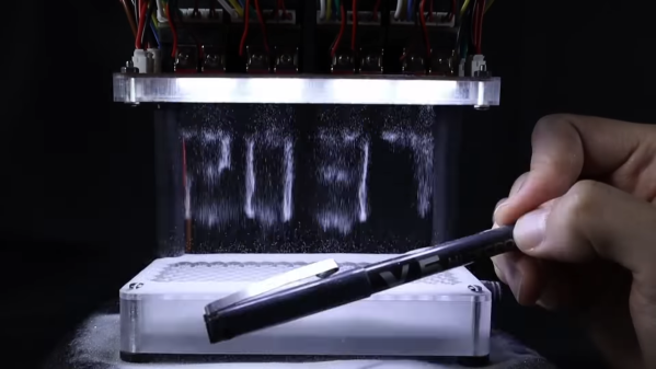
As we recall, what sounded like a good idea was iffy in practice, with low-end optics and either weak incandescent bulbs or blazing LEDs. This nifty VFD projection clock by [Thomas Shupfs] seeks to fix those problems, and from the look of it does a pretty good job. It takes advantage of something else that fell out of favor with consumers — analog photography — by tapping into the ready supply of unwanted lenses. He paired that up with an IVL2-7/5 vacuum fluorescent display inside a 3D printed case with a cone-shaped extension to hold the lens at the right distance above the display. [Thomas] says that the STM32 software only supports JSON-RPC over USB at this time, and includes a couple of Python programs with examples of how to set the time and check the accuracy of the clock.

[Thomas] compares the clock head-to-head against his old LED projection clock, as seen in the featured image above; we flipped it for a better idea of what it would look like from bed. We’ve got to say the soft blue glow of the VFD would be a lot more pleasant to wake up to than the bright red LED projection. But this soft white projection clock is nice too.

Thanks to [skymab] for the tip.

Hackaday Links Column Banner

Hackaday Links: November 12, 2023

Somebody must really have it in for Cruise, because the bad press just keeps piling up for the robo-taxi company. We’ve highlighted many of the company’s woes in this space, from unscheduled rendezvous with various vehicles to random acts of vandalism and stupid AI pranks. The hits kept coming as California regulators pulled the plug on testing, which finally convinced parent company General Motors to put a halt to the whole Cruise testing program nationwide. You’d think that would be enough, but no — now we learn that Cruise cars had a problem recognizing children, to the point that there was concern that one of their autonomous cars could clobber a kid under the right conditions. The fact that they apparently knew this and kept sending cars out for IRL testing is a pretty bad look, to say the least. Sadly but predictably, Cruise has announced layoffs, starting with the employees who supported the now-mothballed robo-taxi fleet, including those who had the unenviable job of cleaning the cars after, err, being enjoyed by customers. It seems a bit wrongheaded to sack people who had no hand in engineering the cars, but then again, there seems to be a lot of wrongheadedness to go around.

Continue reading “Hackaday Links: November 12, 2023”

Leaky SMD Electrolytics? Try These Brute Force Removal Methods

When you say “recapping” it conjures up an image of a dusty old chassis with point-to-point wiring with a bunch of dried-out old capacitors or dodgy-looking electrolytics that need replacement. But time marches on, and we’re now at the point where recapping just might mean removing SMD electrolytics from a densely packed PCB. What do you do then?

[This Does Not Compute]’s answer to that question is to try a bunch of different techniques and see what works best, and the results may surprise you. Removal of SMD electrolytic caps can be challenging; the big aluminum can sucks a lot of heat away, the leads are usually pretty far apart and partially obscured by the plastic base, and they’re usually stuffed in with a lot of other components, most of which you don’t want to bother. [TDNC] previously used a hot-air rework station and liberally applied Kapton tape and aluminum foil to direct the heat, but that’s tedious and time-consuming. Plus, electrolytics sometimes swell up when heated, expelling their corrosive contents on the PCB in the process.

As brutish as it sounds, the solution might just be as simple as ripping caps off with pliers. This seems extreme, and with agree that the risk of tearing off the pads is pretty high. But then again, both methods seemed to work pretty well, and on multiple boards too. There’s a catch, though — the pliers method works best on caps that have already leaked enough of their electrolyte to weaken the solder joints. Twisting healthier caps off a PCB is likely to end in misery. That’s where brutal method number two comes in: hacking the can off the base with a pair of flush cutters. Once the bulk of the cap is gone, getting the leads off the pad is a simple desoldering job; just don’t forget to clean any released schmoo off the board — and your cutters!

To be fair, [This Does Not Compute] never seems to have really warmed up to destructive removal, so he invested in a pair of hot tweezers for the job, which works really well. But perhaps you’re not sure that you should just reflexively replace old electrolytics on sight. If so, you’re in pretty good company.

Continue reading “Leaky SMD Electrolytics? Try These Brute Force Removal Methods”

Neopixels? Try Liquid Nitrogen To Color Shift Your LEDs Instead

If you’re like us, you’ve never spent a second thinking about what happens when you dunk an ordinary LED into liquid nitrogen. That’s too bad because as it turns out, the results are pretty interesting and actually give us a little bit of a look at the quantum world.

The LED fun that [Sebastian] over at Baltic Lab demonstrates in the video below starts with a bright yellow LED and a beaker full of liquid nitrogen. Lowering the powered LED into the nitrogen changes the color of the light from yellow to green, an effect that reverses as the LED is withdrawn and starts to warm up again. There’s no apparent damage to the LED either, although we suppose that repeated thermal cycles might be detrimental at some point. The color change is quite rapid, and seems to also result in a general increase in the LED’s intensity, although that could be an optical illusion; our eyes are most sensitive in the greenish wavelengths, after all.

So why does this happen? [Sebastian] goes into some detail about that, and this is where quantum physics comes into it. The color of an LED is a property of the bandgap of the semiconductor material. Bandgap is just the difference in energy between electrons in the valence band (the energy levels electrons end up at when excited) and the conduction band (the energy levels they start at.) There’s no bandgap in conductive materials — the two bands overlap — while insulators have a huge bandgap and semiconductors have a narrow gap. Bandgap is also dependent on temperature; it increases with decreasing temperature, with different amounts for different semiconductors, but not observably so over normal temperature ranges. But liquid nitrogen is cold enough for the shift to be dramatically visible.

We’d love to see the color shift associated with other cryogens, or see what happens with a blue LED. Want to try this but don’t have any liquid nitrogen? Make some yourself!

Continue reading “Neopixels? Try Liquid Nitrogen To Color Shift Your LEDs Instead”

Solder Two Boards At Once With This Dual Reflow Plate

Homebrew reflow projects generally follow a pretty simple formula: find a thrift shop toaster oven or hot plate, add a microcontroller and a means to turn the heating element on and off, and close the loop with a thermistor. Add a little code and you’re melting solder paste. Sometimes, though, a ground-up design works better, like this scalable reflow plate with all the bells and whistles.

Now, we don’t mean to hate on the many great reflow projects we’ve seen, of course. But [Michael Benn]’s build is pretty slick. The business end uses 400-watt positive temperature coefficient (PTC) heating elements from Amazon controlled by solid-state relays, although we have to note that we couldn’t find the equivalent parts on the Amazon US site, so that might be a problem. [Michael] also included mechanical temperature cutoffs for each plate, an essential safety feature in case of thermal runaway. The plates are mounted at the top of a 3D-printed case, which also has an angled enclosure for a two-color OLED display and a rotary encoder.

The software runs on an ESP32 and supports multiple temperature profiles for different solder pastes. The software also supports different profiles on the two plates, and even allows for physical expansion to a maximum of four heating plates, or even just a single plate if that’s what you need. The video below shows it going through its paces along with the final results. There’s also a video showing the internals if that’s more your style

We appreciate the fit and finish here, as well as the attention to safety. Can’t find those heating elements for your build? You might have to lose your appetite for waffles.

Continue reading “Solder Two Boards At Once With This Dual Reflow Plate”