Building A Sinclair ZX81 In 2022 With All New Parts

As the supply of genuine retrocomputers dwindles and their prices skyrocket, enthusiasts are turning their eyes in other directions to satisfy their need for 8-bit pixelated goodness. Some take the emulation route, but others demand a solution that’s closer to the original hardware. Following the latter path, [iNimbleSloth] is answering the question as to whether it’s possible to build a Sinclair ZX81 from all-new parts in 2022.

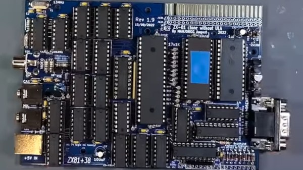
The ZX81 was Sir Clive’s second Z80-based computer, and its low price made it an instant success which paved the way for the legendary ZX Spectrum. From here in 2022 the original Ferranti ULA chip that contained all the logic is unobtainable except by raiding another ’81, so he’s using a design that has the same functionality in 74 series logic. The PCB is the same size as the original, and he’s paired it with a keyboard PCB using tactile switches. The video below the break is the first of what is to be a series, and he will be looking at a readily available 3D printed ZX81 case and the re-manufactured membrane keyboard.

For those of us who first learned to code in its meager 1k of memory the ’81 will always be a special computer. Sure it had many faults, but simply having an affordable real computer at all in 1981 was special. To see one being made from scratch is special then, and it would be nice to think that a few other people might learn how a computer works the Sinclair way.

Continue reading “Building A Sinclair ZX81 In 2022 With All New Parts”

Three Norths Align, And It’s Not Even Up North

Sometimes here at Hackaday we bring you stories from slightly outside our world of tech, because they have an interesting angle. Maybe they relate to science or astronomy, or in the case of the UK’s Ordnance Survey explaining how Britain’s three Norths will align, geography.

Some of you may know that the British monarch has two birthdays, but three Norths, what on earth is going on? You’ll guess that two of them are true North, pointing to the North Pole, and magnetic North, pointing to the Earth’s north magnetic field, but how about the third? It’s grid North — the north of the country’s mapping grid system in which the curved surface is projected onto a flat sheet.

It aligns with true North at 2 degrees West of Greenwich, and the news is that for the first time ever due to movement of the magnetic North Pole, the three different Norths will align at a point in the south of England. Magnetic North has been on the move at some pace over the last few decades, from a position somewhere in the Canadian Arctic islands northwards, and it so happens that for Brits its direction is briefly aligned with our view of the Pole. The Ordnance Survey story is of some interest, but for a wealth of information it’s worth consulting NASA. Take a look at the video below the break.

Continue reading “Three Norths Align, And It’s Not Even Up North”

How Those NES DIP Chips Were Reduced To QFNs

The world of console modding leads us to some extremely impressive projects, and a recent one we featured of note was a portable NES produced by [Redherring32]. It was special because the original NES custom DIP chips had been sanded down to something like a surface-mount QFN package. Back when our colleague [Arya] wrote up the project there wasn’t much information, but since then the full details have been put up in a GitHub repository. Perhaps of most interest, it includes a full tutorial for the chip-sanding process.

To take irreplaceable classic chips and sand them down must take some guts, but the premise is a sound enough one. Inside a DIP package is a chip carrier and a web of contact strips that go to the pins, this process simply sands away the epoxy to expose those strips for new contacts. The result can then be reflowed as would happen with any QFN, and used in a new, smaller NES.

Along the way this provides a fascinating insight into DIP construction that most of us never see. If any of you have ever managed to fatigue a pin off a DIP, you’ll also no doubt be thinking how the technique could be used to reattach a conductor.

You can read our original coverage of the project here.

A Pi Pico Oscilloscope

At the budget end of the oscilloscope range lie the so-called pocket ‘scopes. About the size of a deck of cards, they combine a microcontroller and an LCD screen to make an instrument with a bandwidth in the tens of kilohertz and a not-too-sparkling performance. They’re something of a toy, but then again, if all that’s needed is a simple ‘scope for audio frequencies, they make a passable choice in a small package. Now [jgpeiro] has made one which is light years ahead of the toy kits, using a Raspberry Pi Pico, a 100 MHz ADC, and an effort to design a better input circuit.

At its simplest this could be a straightforward op-amp and ADC circuit feeding the Pico, but instead it has multiple stages carefully designed to offer the full bandwidth, and with gain, offset, and trigger settings being set by a series of DAC chips under software control. This and the decent bandwidth make this a much more viable oscilloscope, and one we’d like to see further developed.

By comparison, we took a look at the best of the competition a few years ago.

Wall Art With A Moving Coil Or Two

Almost every type of retro indicator technology from a Nixie tube to a flipdot with everything else in between has found itself on these pages in some form of artwork or decoration. It’s pleasing then to see one that hasn’t appeared so much over the years, and particularly at the hands of our colleague [Voja Antonic]. He’s taken a large array of moving-coil panel meters and hooked them up to a microcontroller board that’s triggered by a PIR sensor. Normally the readings are random, but get too close to it and all those needles start moving, making for a very different take on an electronic wall display.

He’s not given us the details of the control circuit he’s used, but in a sense that matters little. We think any Hackaday reader who knows one end of a soldering iron from the other should be able to produce a small DC current from a DAC to drive a meter, and we don’t think the software to make random readings would trouble many of you either.

Meanwhile [Voja] has produced so many interesting projects over the years, not least the 2022 Superconference badge. Here’s one from a few years ago.


When Only A TO92 Will Do

As through-hole components are supplanted by their surface-mount equivalents, we’re beginning to see the departure of once-common component form factors. Many such as the metal can transistors became rare years ago, while others still hang on albeit in fewer and fewer places. One of these is the once-ubiquitous TO92 moulded plastic transistor, which we don’t see very much of at all in 2022. [Sam Ettinger] is a fan of the D-shaped plastic blobs, and has gone as far as to recreate them for a new generation to enjoy.

Though a TO92 was a relatively miniature package in its day, it’s still large enough to easily fit a SOT23 or similar SMD packaged device on a small PCB. So the tiny board with just enough space for the part and the three wires was fabricated, ready for encapsulating. Epoxy moulding a TO92 gave very poor results, so instead an SLA print of a T092 shell was made. It fits neatly over the PCB, producing a perfect TO92 package. We’re sure a translucent pink package would have raised a few eyebrows back in the 1960s though.

There will come a time when restorers of old electronics will use and refine this technique to replace dead components. We’ve seen the technique before, after all.

Pieca Is A Pi Camera With Some Very Nice Lenses

The advent of the high-quality version of the Raspberry Pi camera has given experimenters a good-enough quality camera system that they can use it to create better devices than mere snapshot cameras. It’s been used by experimenters for some exciting projects, but so far, very few of them have broken away from the Pi camera’s C-mount lens system. [Tom Schucker]’s Pieca is an interesting departure then, because it takes the Pi HQ camera into new territory by using Leica rangefinder lenses.

There are enough Pi camera projects that by now the process of setting one up should be pretty well known. This one is a bit different in its use of a focal length reducer, mounted inside a 3D-printed Leica lens mounting plate. The result is that the Leica lens is better matched to the much smaller size of the Pi camera sensor compared to a 35mm frame.

The camera’s aesthetic design is on the chunky side, probably because of the choice of a Pi 4 rather than a Pi Zero. It remains very usable though, and produces photographs with a distinctive feel. You can see more in the video below the break. Meanwhile if you aren’t lucky enough to own a stable of Leica lenses, perhaps you could think about adapting more common optics? We’ve seen it before with the original Pi camera.

Continue reading “Pieca Is A Pi Camera With Some Very Nice Lenses”