If you were an Amiga enthusiast back in the day, the chances are you had an Amiga 500, and lusted after a 2000 or maybe later a 3000. Later still perhaps you had a 600 or a 1200, and your object of desire became the 4000. The amusingly inept Commodore marketing department repackaged what was essentially the same 68000-based Amiga at the bottom end of the range through the platform’s entire lifetime under their ownership, with a few minor hardware upgrades in the form of chipset revisions that added a relatively small number of features.
We’ve probably listed above all the various Amigas you’ll be familiar with, with a few exceptions you either didn’t have or only saw in magazines. The original A1000, the chipset-upgraded A500+, the CDTV multimedia platform, or the CD32 games console as examples. But there’s one we haven’t listed which you may never have seen unless you hail from the United Kingdom, and it’s an Amiga behind which lies a fascinating tale that has been unearthed by [RetroManCave].
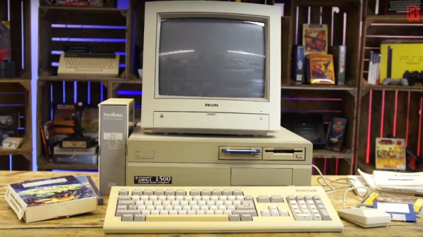
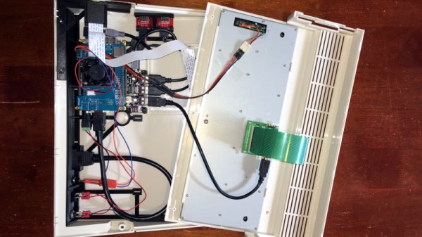
In the late 1980s, Commodore sold the A500 all-in-one cased Amiga to consumers with marketing based heavily upon gaming, and the A2000 desktop Amiga to businesses with the promise of productivity software. Both machines had a 16-bit Motorola 68000 running at the same speed, with the A2000 having a lot of extra memory and a hard drive lurking within that case. The price difference between the two was inordinately high, creating a niche for an enterprising British company called Checkmate Computers to fill with their provocatively named A1500, a clever case for an A500 mainboard that gave it an expansion slot and space for that hard drive and memory.
This machine’s existence angered Commodore, to the extent that they vowed to eradicate the upstart by releasing their own UK-only A1500. The result, a comically badly concealed rebadge of an A2000 with two floppies and no hard drive, is something we remember seeing at the time, and dare we admit it, even lusting after. But the full story in the video below is well worth a watch for an engrossing insight into a little-known saga in one corner of the computing world during the 16-bt era. Towards the end it becomes a plug for the Checkmate Computers co-founder’s current Kickstarter project, but if that holds no interest for you then you are at least forewarned.
Of course, if you have either A1500 today, you might want an up-to-date graphics card for it.
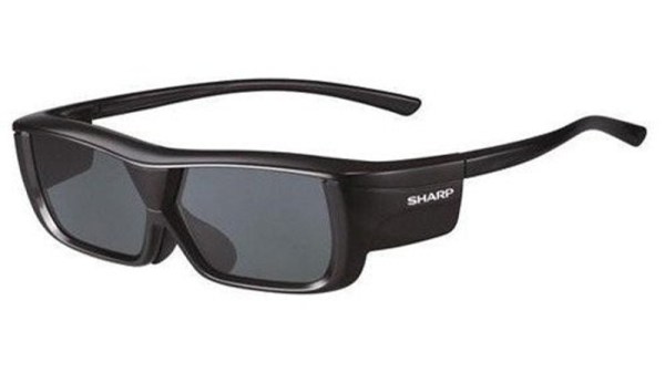
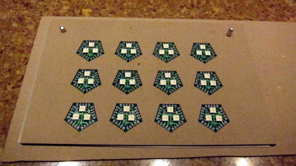
 Of course, once everyone had seen the film with the blue aliens and tried a few other titles on their new toy, they grew tired of headaches, nausea, and half-brightness. The glasses gathered dust, and the fancy 3D telly never ventured beyond two dimensions again. Except for [Bobricius’s] glasses, that is, for he’s levered out the 3D driver electronics and replaced them with a tiny SOIC-8 solar cell. Light hits the cell, the LCD gets a charge and darkens, no light and they remain transparent. Similar to welding goggles — though they usually use a battery. It’s unclear whether they can get a little too dark on a really bright day and whether they are something akin to