It is probable that many of us have noticed a variety of very cheap CNC mills in the pages of Chinese tech websites and been sorely tempted. On paper or as pixels on your screen they look great, but certainly with the more inexpensive models there soon emerges a gap between the promise and the reality.
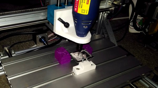
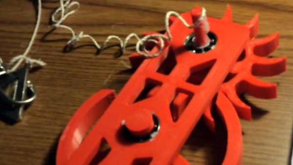
[Brandon Piner] hopes to address this problem, with his CNC Mod Pack, a series of upgrades to a cheap mill designed to make it into a much more useful tool. In particular he’s created a revised 3D-printed tool holder and a set of end stop switches. The tool holder boasts swappable mounts on a dovetail fitting with versions for both a laser diode and a rotary tool, allowing much better tool positioning. Meanwhile the end stops are a necessary addition that protects both tool and machine from mishaps.
The same arguments play out in the world of small CNC mills as do in that of inexpensive 3D printers, namely that the economy of buying the super-cheap machine that is nominally the same as the expensive one starts to take a knock when you consider the level of work and expense needed to make your purchase usable. But with projects like this one the barrier to achieving a quality result from an unpromising start is lowered, and the enticing prospect is raised of a decent CNC machine for not a lot.


![[Paul] showing off some of the Pimoroni attention to design detail. This artwork is hidden behind a display panel on the finished product.](https://hackaday.com/wp-content/uploads/2018/05/pimoroni-paul.jpg)