A common sight in the days before cheap PCs conquered the world was the dumb terminal. A keyboard and a monitor with a serial port on the back that was usually hooked up to a minicomputer or even a mainframe, these were simple devices. Anything that came into the serial port was rendered on the screen, anything typed on the keyboard was sent out through the serial port. They didn’t need to contain a microprocessor. If you are old enough, you may remember electronics magazines of the 1970s and early 1980s publishing terminal designs based entirely on 74 series logic.
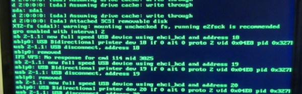
The serial terminal might seem like a redundant historical footnote when viewed from 2016, but they can still find a use among those working with systems such as small embedded microcontrollers that only possess a serial port. To address this application, Hackaday.io user [K.C.Lee] has created a low-cost terminal module for a VGA monitor and a PS/2 keyboard based around an inexpensive STM32F030F4 processor.
Have you ever had to write a bit of code to interpret a non-linear analog reading as picked up by an ADC? When all you have to work with for your transfer function is a graph in a semiconductor datasheet that was probably written thirty years ago and prints out the size of a postage stamp, that’s a rather annoying task. Wouldn’t it be nice if you had access to the numbers behind the graph!
You can’t knock on the office door of the engineer who created it back in the ’80s, he’s probably in retirement and playing golf or growing prize petunias by now. But you can digitize the graph to get yourself a lot closer to the action, and to help you in your quest there’s a handy online tool.
2N3904 current gain
WebPlotDigitizer is not new, it’s been around for quite a few years now. But it’s still worth talking about, because it’s one of those tools to keep in reserve. If you’ve ever needed it, you’ll know what we mean.
So how does it work? Load an image with a graph in it, select some points on the X and Y axis, roughly trace the curve with a marker tool, and set it in motion. Let’s give it a go. We’re going to try digitizing the current gain plot from the 2N3904 datasheet (PDF) that we examined a few days ago.
Data points!
So, open the WebPlotDigitizer app, load the graph image captured from the sheet as a JPEG. It asks what type of graph you’ve loaded, in this case a 2D X-Y plot. It asks you to identify four known points on the axes and supply their values. You also tell it if the axes are logarithmic at this point. Select “Automatic mode” on the right hand side, then click “Pen” and mark the graph trace, then select the colour of the trace. Click the “Run” button, and your data points appear. Hit the “View data” button, and there you have it. A few rogue points to remove perhaps, but it does a pretty good job.
It is often a surprise to see how other people react to mains electricity when they encounter it in a piece of equipment. As engineers who have dealt with it both personally and professionally for many years it is easy to forget that not everyone has had that experience. On one hand we wince at those who dive in with no fear of the consequences, on the other we are constantly surprised at the number of people who treat any item with more than a few volts in it as though it was contaminated with radioactive anthrax and are scared to even think about opening it up.
We recently had a chat among the Hackaday writers about how we could approach this subject. The easy way out is to be all Elf-and-Safety and join the radioactive anthrax crowd. But the conclusion we came to was that this site is a resource for hackers and makers. Some of you are going to lift the lid on boxes containing significant voltages no matter what, so we thought we’d help you do it safely rather than just listen for the distant screams.
So here follows the first in a series on how to approach electronic devices containing high voltages, and live to tell the tale. By “high voltages” we mean anything up to mains voltages, and those directly derived from them such as the few hundred volts rectified DC you’ll find in a switch-mode PSU. For multi-kilovolt EHT you’ll have to wait for another article, because that is an entire subject in itself. We’ll mention these higher voltages in passing, but their detail is best left for a Hackaday colleague with more pertinent experience.
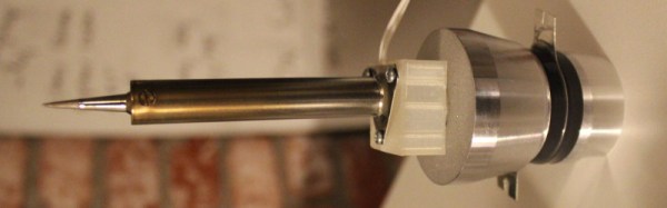
One of the most interesting facets of our community of hackers and makers comes from its never-ending capacity to experiment and to deliver new technologies and techniques. Ample demonstration of this came this morning, in the form of [Hunter Scott]’s Hackaday.io project to create an ultrasonic soldering iron. This is a soldering technique in which the iron is subjected to ultrasonic vibrations which cavitate the surface of the materials to be soldered and remove any oxides which would impede the adhesion of the solder. In this way normally unsolderable materials such as stainless steel, aluminium, ceramic, or glass can be soldered without the need for flux or other specialist chemicals. Ultrasonic soldering has been an expensive business, and [Hunter]’s project aims to change that.
This iron takes the element and tip from a conventional mains-powered soldering iron and mounts it on the transducer from an ultrasonic cleaner. The transducer must be given an appropriate load which in the case of the cleaner is furnished by a water bath, or it will overheat and burn out. [Hunter]’s load is just a soldering iron element, so to prevent transducer meltdown he keeps the element powered continuously but the transducer on a momentary-action switch to ensure it only runs for the short time he’s soldering. The project is not quite finished so he’s yet to prove whether this approach will save his transducer, but we feel it’s an interesting enough idea to make it definitely worth following.
This is the first ultrasonic soldering project we’ve featured here at Hackaday. We have however had an ultrasonic plastic welder before, and an ultrasonic vapour polisher for 3D prints. It would be good to think this project could spark a raft of others that improve and refine DIY ultrasonic soldering designs.
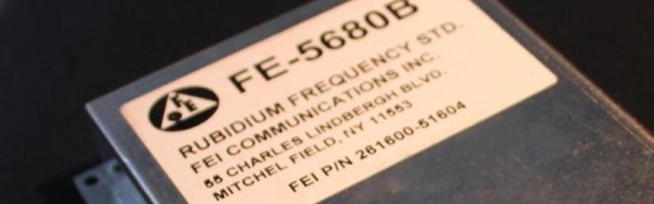
Sometimes you open a freshly created Hackaday.io project and discover more than you expect. A moment of idle curiosity turns into a lengthy read involving several projects you wonder how you managed to miss the first time around. So it was this morning, with [Yann Guidon]’s documentation of his eBay-purchased rubidium frequency standard. In itself an interesting write-up, with details of reverse engineering the various different internal clock signals to derive more than just the standard 1-second pulses, and touching on the thermal issues affecting frequency lock.
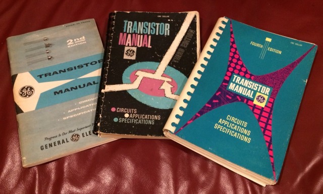
Transistors were EXCITING back then!
It is when you look at his intended use for the standard that you’ll see the reason for the lengthy read. He has a couple of discrete component clock projects on the go. His first, a low-powered MOSFET design, promises to break the mold of boring silicon bipolar transistors with hefty power consumption. It is his second, a design based on germanium transistors and associated vintage components, that really stands apart. Not a Nixie tube in sight, but do browse the project logs for a fascinating descent into the world of sourcing vintage semiconductors in 2016.
Neither clock project is finished, but both show significant progress and they’ll certainly keep time now that they’ll be locked to a rubidium standard. Take a look, and keep an eye on progress, we’re sure there will be more to come.
The mass media are funny in the way they deal with new technology. First it’s all “Wow, that’s Cool!”, then it’s “Ooh, that’s scary”, and finally it’s “BURN THE WITCH!”. Then a year or so later it’s part of normal life and they treat it as such. We’ve seen the same pattern repeated time and time again over the years.
The mass media tech story cycle. Our apologies to Gartner. Curve image: Jeremykemp [ CC BY-SA 3.0 ], via Wikimedia CommonsSeasoned readers may remember silly stories in the papers claiming that the Soviets could somehow use the technology in Western 8-bit home computers for nefarious purposes, since then a myriad breathless exclusives have predicted a youth meltdown which never materialised as the inevitable result of computer gaming, and more recently groundless panics have erupted over 3D printing of gun parts. There might be a British flavour to the examples in this piece because that’s where it is being written, but it’s a universal phenomenon wherever in the world technologically clueless journalists are required to fill column inches on technical stories.
The latest piece of technology to feel the heat in this way is the multirotor. Popularly referred to as the drone, you will probably be most familiar with them as model-sized aircraft usually with four rotors. We have been fed a continuous stream of stories involving tales of near-misses between commercial aircraft and drones, and there is a subtext in the air that Something Must Be Done.
Are multirotors unfairly being given bad press? It certainly seems that way as the common thread among all the stories is a complete and utter lack of proof. But before we rush to their defence it’s worth taking a look at the recent stories and examining their credibility. After all if there really are a set of irresponsible owners flying into commercial aircraft then they should rightly be bought to book and it would do us no favours to defend them. So let’s examine each of those incident reports from that BBC story.
We’re all familiar with semiconductor devices, and we should remember the explanation from high-school physics classes that they contain junctions between two types of semiconductor material. “N” type which in the for-schoolchildren explanation has a surplus of electrons, and “P” type which has “Holes”, or a deficit of electrons.
Unless our careers have taken us deep into the science of the semiconductor industry though that’s probably as close as we’ve come to the semiconductors themselves. To us a diode or a transistor is a neatly packaged device with handy wires. We’ve never really seen what’s inside, let alone made any real semiconductor devices ourselves.
What makes his experiments particularly impressive though is not merely that he’s created a working diode, albeit one with a low reverse breakdown voltage. He’s done it not in a gleaming laboratory with a full stock of chemicals and equipment, but on his bench with a candle, and drops of water. He takes us through the whole process, with full details of his semiconductor manufacture as well as his diode test rig to trace the device’s I/V curve. Well worth a read, even if you never intend to make a diode yourself.






![The mass media tech story cycle. Our apologies to Gartner. Curve image: Jeremykemp [ CC BY-SA 3.0 ], via Wikimedia Commons](https://hackaday.com/wp-content/uploads/2016/04/media-tech-cycle-800px1.png)