Visualizing LEDs For More Efficient Pin Packing

The archetypal “blink an LED” is a great starter project on any platform, but once the bug takes hold that quickly turns into an exploration of exactly how many LEDs a given microcontroller can drive. And that often leads to Charlieplexing. A quick search yields many copies of The Table describing how many LEDs can be driven by a given number of pins but that’s just the most rudimentary way to describe it. Way back in 2013 [M Rule] developed a clever trick to describe the number of LED matrices which can be driven by a Charlieplexed array of a given size that makes this process much more intuitive. The post may be old, but we promise the method is still fresh.

[M Rule] was specifically looking to drive those big, cheap single color LED matrices which are often used to make scrolling signs and the like. These parts are typically a matrix of LEDs with a row of common cathodes and one of common anodes. Internally they are completely dumb and can be driven by row/column scanning, or any other way a typical matrix can be controlled. The question is, given known matrix sizes, how many can be driven with a a number of Charlieplexed LED drive pins?

The first step is to visualize the 1D array of available pins as a 2D matrix, as seen to the right. Note each numbered pin is the same on the X and Y, thus the black exclusion zone of illegal drive pin combinations slicing across the graph (you can’t drive an LED connected to one pin twice). The trick, if one were to say it resides in a single place, would be titling the axis anode and cathode, representing two “orientations” the drive pins can be put in. With this diagram [M Rule] observed you can simply drop a matrix into the array. If it fits outside the exclusion zone, it can be driven by those pins!
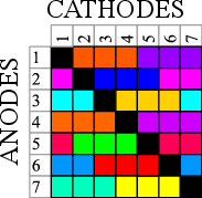
To the left is what this looks like with two 8×8 matrices, one connected between pins 1-8 and 9-16, the other connected between 9-16 and 1-8. This isn’t terribly interesting, but the technique works just as well with single LEDs and any size matrix, including 7-segment displays. Plus as long as an element doesn’t overlap itself it can wrap around the edges leading to some wild visuals, like 14 RGB LEDs on seven pins to the right.

The most extreme examples are pretty exotic. Check out [M Rule]’s post for the crown jewel; 18 pins to drive six 5×7 modules, six 7-segment displays, 12 single LEDs, and 18 buttons!

If this color coded diagram seems familiar, you may be remembering [openmusiclabs]’ excellent diagram describing ways to scan many of buttons. Or our coverage of another trick of matrix topology by [M Rule] from a few weeks ago.

Homemade Magic Makes The Metcal Go

First soldering irons are often of the Radioshack or Maplin firestarter variety. They’re basically wall power shorted across a nichrome heater or similar with some inline resistance to make it harder to burn down the house. You plug them in, the current flows, and they get hot. Done.

If you stick with the hobby for a while, these eventually get replaced with something like the venerable HAKKO FX-888D or that one Weller everyone likes with the analog knob. These are much improved; having temperature control leads to a more consistently heated tip and much improved soldering experience.

Entering the electronics workplace one comes across the next level of quality soldering iron: high end HAKKOs, Metcals, JBCs, and the like. Using one of these irons is practically a religious experience; they heat in a flash and solder melts while you blink. They even turn off when you put the handpiece down! But they’re expensive to buy (hint: think used). What’s a hobbyist to do?

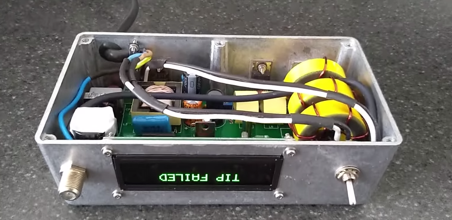
[SergeyMax] seems to have had this problem. He bit the bullet, figured out how the Metcal works, and made his own base. This is no mean feat as a Metcal might look like a regular iron but it’s significantly more complex than ye olde firestarter. The Metcal magic is based on a oscillating magnetic fields (notice the handpiece is connected via BNC?) interacting with a tip bearing a special coating. In the presence of the changing field the tip heats up until it hits its Curie temperature, at which point it stops interacting with the magnetic field and thus stops heating.

When the user solders, the tip cools by sinking its heat into the part and drops below the Curie temperature again, which starts the heating again. It’s like temperature control with the sensor placed absolutely as close to the part as possible and a nearly instant response time, without even a control loop! [SergeyMax] has a much more thorough description of how these irons work, which we definitely recommend reading.

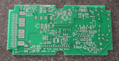
So what’s the hack? Based on old schematics and some clever reverse engineering from photos [SergeyMax] built a new base station! The published schematic is as rich with capacitors and inductors as one could hope. He didn’t post source or fab files but we suspect the schematic and photos of the bare board combined with some tinkering are enough for the enterprising hacker to replicate.

The post contains a very thorough description of the reverse engineering process and related concerns in designing a cost efficient version of the RF circuitry. Hopefully this isn’t the last Metcal replacement build we see! Video “walkthrough” after the break.

Edit: I may have missed it, but eagle eyed commentor [Florian Maunier] noticed that [SergeyMax] posted the sources to this hack on GitHub!

Continue reading “Homemade Magic Makes The Metcal Go”

Tokyo Mechanical Keyboard Meetup Knocks Our Clacks Off

Just a few days ago, on the other side of the planet from this author, there was a mechanical keyboard meetup in Tokyo. Fortunately through the magic of the Internet we can all enjoy the impressive collection of devices people brought, and boy were there some interesting specimens. There were certainly the inevitable collections of strange artisan keycaps, unusual handmade switches, and keycap sets only available in one group buy five years ago in Nicaragua. But among the bright colors were some truly unique custom designs the likes of which we haven’t see before. A single source is hard to credit, you could check the hashtag #tokyomk6 on Twitter, or [obra]’s thread of photos, or this great blog post (video walkthroughs and photos included) from [romly].

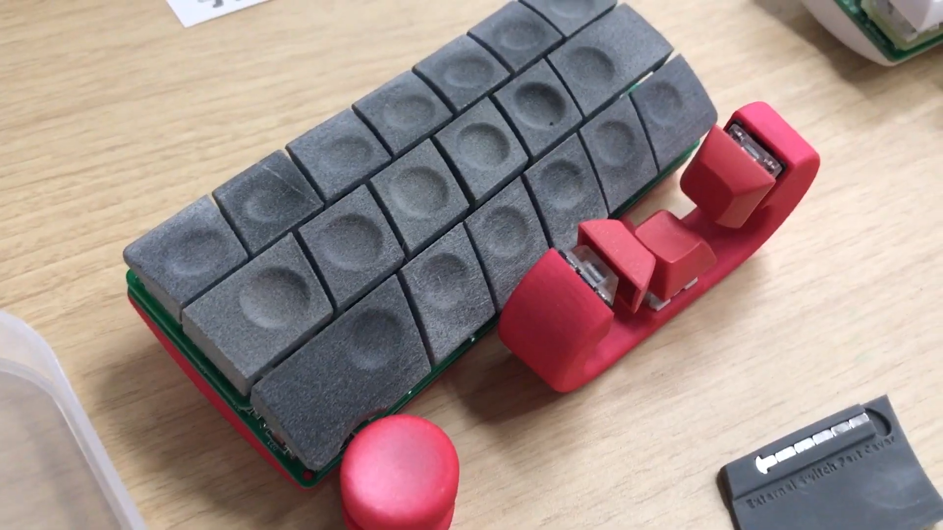
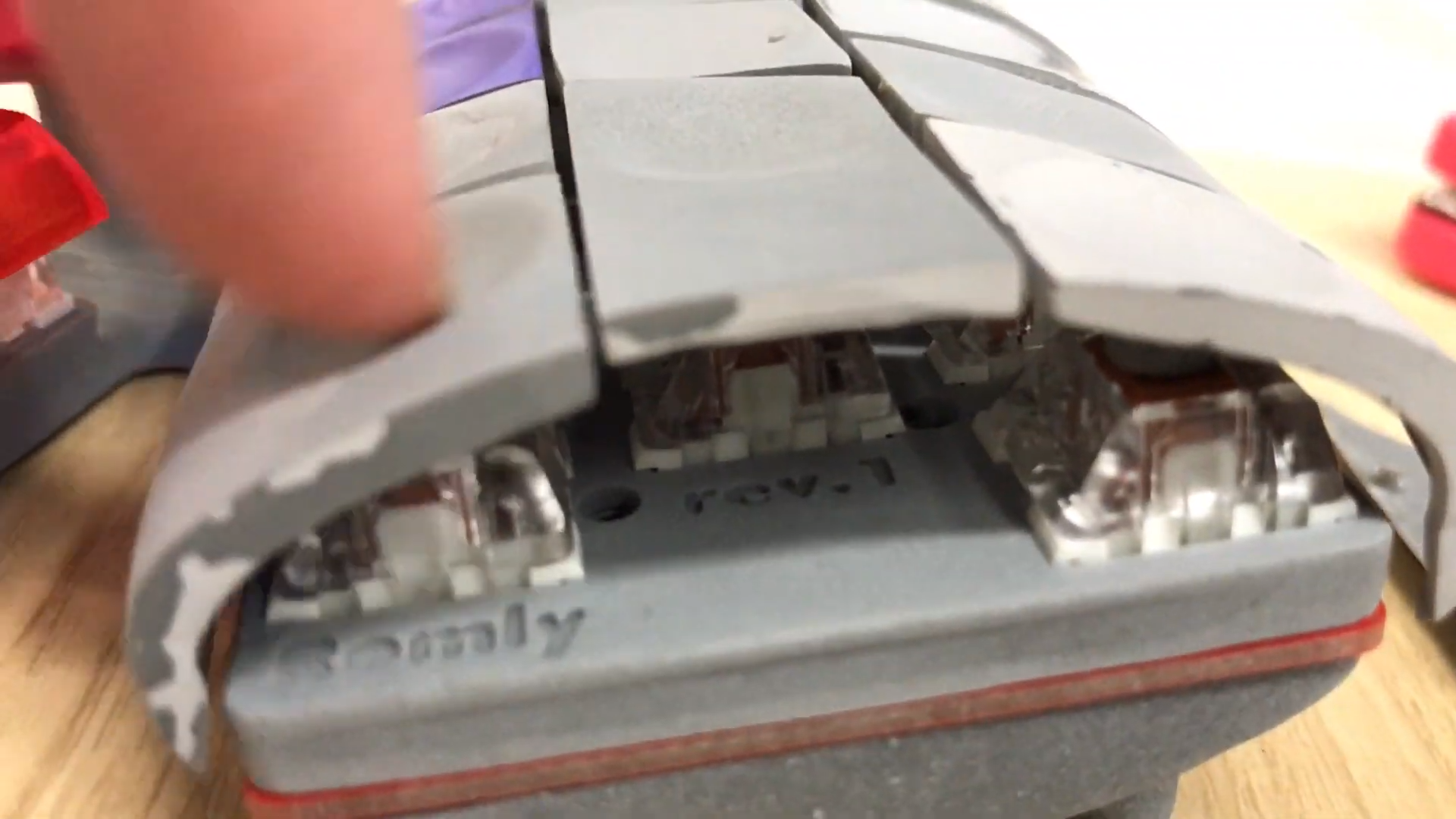
Speaking of [romly], one of their designs stands out as particularly unusual. There are a few things to note here. One is the very conspicuous surface profile of the (clearly totally custom) keycaps themselves. Instead of flat or cylindrical or spherical, these are round. Round like the outside of a log. If we didn’t know better it might look like the entire thing was sculpted or extruded as a single unit. And just below the deck are the perpendicular thumb clusters. Frankly we aren’t sure how to refer to this design feature. The switches are mounted at right angles facing inward so the user places a thumb inside it in a style reminiscent of the DataHand. It’s quite interesting, and we’d be love to know more about what specific functionality it provides.
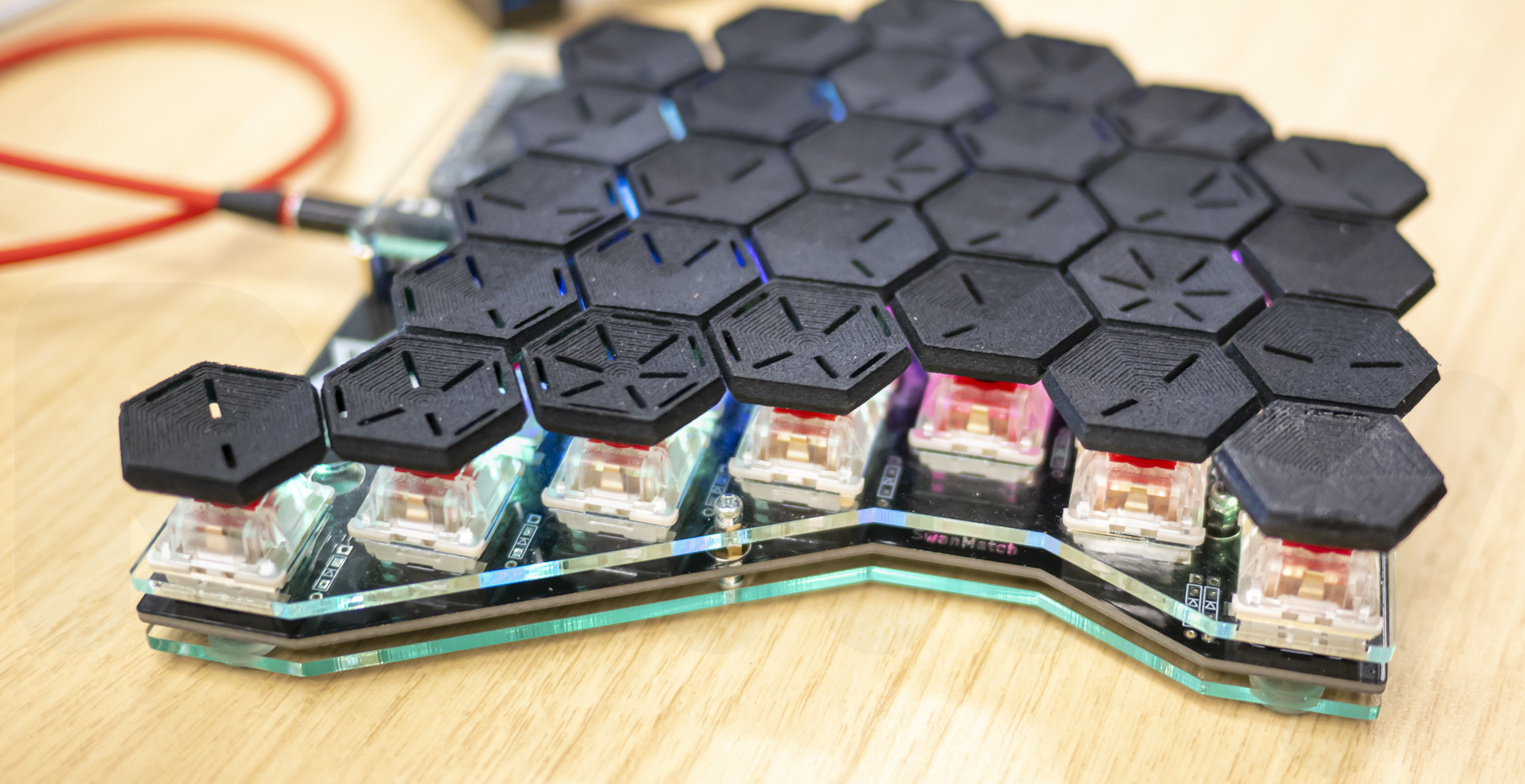
Another interesting entrant is this keyboard with unusually staggered switches and hexagonal caps (check out the individual markings!). Very broadly there are two typical keyboard layout styles; the diagonal columns of QWERTY (derived from a typewriter in the 1800’s) or the non slanted columns of an “ortholinear” or matrix style layout. By those metrics this is something like an ortholinear keyboard in that its switches overlap their neighbors by half, but the edge to edge close packed caps imply that it might be something else.  We’d be very interested to know how typing on this beast would be!
There were so many more awesome designs present at the meetup that this would never end if we tried to document them all. Take a look through the posts and call out anything else too excellent to go unnoticed!

Thanks [obra] for Tweeting about this so we could discover it.

Lateral Thinking For An Easier Charlieplex

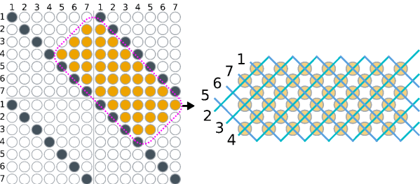
In the practical world we live in, PCBs are often rectangles (or rectangles with rectangles, it’s just rectangles all the way down). When a designer goes to schematic capture things are put down on nice neat grid intersections; and if there isn’t a particular demand during layout the components probably go on a grid too. Routing even the nastiest fractal web of traces is mostly a matter of layers and patience. But if the layout isn’t being done in a CAD tool and needs to be hand assembled free-form this isn’t always as simple. [M Rule] had this very problem and discovered a clever solution, turning things diagonal.

They changed the fitness criteria to the optimization problem that is controlling a lot of LEDs. Instead of minimum pins to drive the goal became “easiest assembly”, which meant avoiding wires snaking back and forth across the layout, a big source of frustration in a big Charlieplexed design. The observation was that if they turned the a rectilinear LED matrix by 45° and wrapped each connection around at the edges it formed what was essentially a large multiplexed matrix. The topology is pretty mind bending, so take a minute to study the illustration and build your mental model.

It looks a little strange, but this display works the same way a normal multiplexed display does but with the added benefit that each trace flows from one side to the other without turning back on itself at any point. To light any LED set the right row/column pair as source/sink and it turns on!

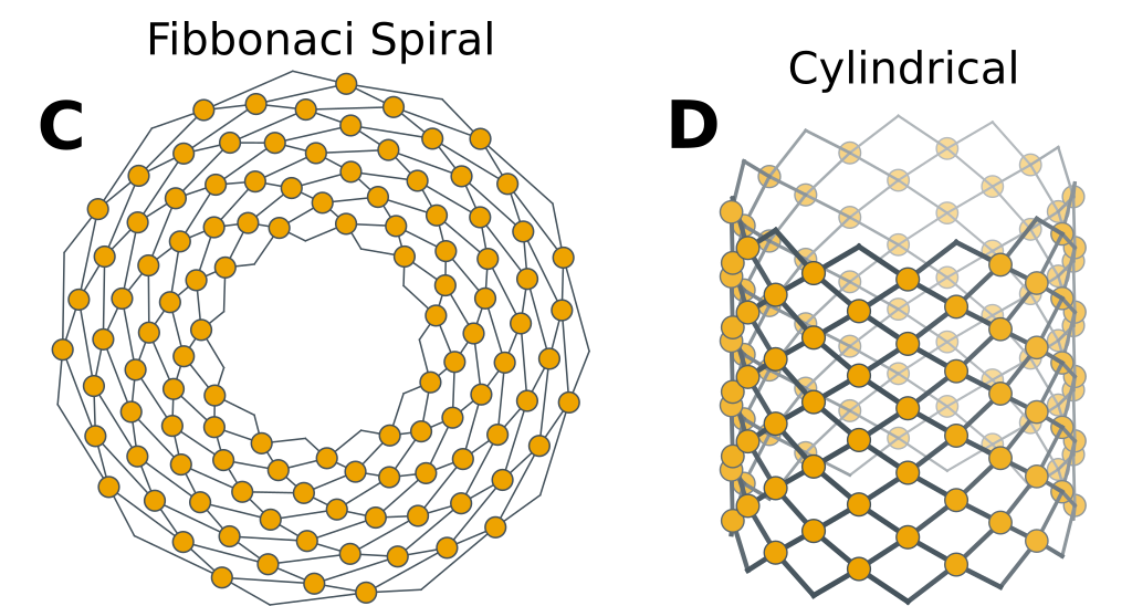
What if you actually need a rectangular display? Well that’s no problem, the matrix can be bent and smooshed as desired to change its shape. At the most extreme the possible display topologies get pretty wild! We’re sure to try thinking laterally next time we need to design an unusual display, maybe there is a more efficient matrix to be found.

Analog Failures On RF Product Cause Production Surprise

A factory is a machine. It takes a fixed set of inputs – circuit boards, plastic enclosures, optimism – and produces a fixed set of outputs in the form of assembled products. Sometimes it is comprised of real machines (see any recent video of a Tesla assembly line) but more often it’s a mixture of mechanical machines and meaty humans working together. Regardless of the exact balance the factory machine is conceived of by a production engineer and goes through the same design, iteration, polish cycle that the rest of the product does (in this sense product development is somewhat fractal). Last year [Michael Ossmann] had a surprise production problem which is both a chilling tale of a nasty hardware bug and a great reminder of how fragile manufacturing can be. It’s a natural fit for this year’s theme of going to production.

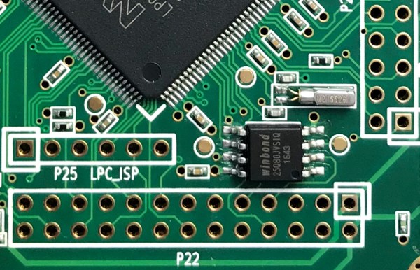
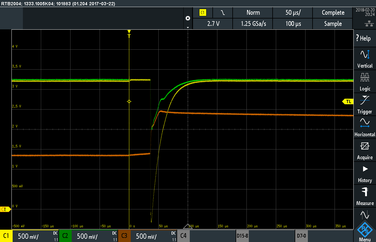
Surprise VCC glitching causing CPU reset

The saga begins with [Michael] receiving an urgent message from the factory that an existing product which had been in production for years was failing at such a high rate that they had stopped the production line. There are few worse notes to get from a factory! The issue was apparently “failure to program” and Great Scott Gadgets immediately requested samples from their manufacturer to debug. What follows is a carefully described and very educational debug session from hell, involving reverse engineering ROMs, probing errant voltage rails, and large sample sizes. [Michael] doesn’t give us a sense for how long it took to isolate but given how minute the root cause was we’d bet that it was a long, long time.

The post stands alone as an exemplar for debugging nasty hardware glitches, but we’d like to call attention to the second root cause buried near the end of the post. What stopped the manufacturer wasn’t the hardware problem so much as a process issue which had been exposed. It turned out the bug had always been reproducible in about 3% of units but the factory had never mentioned it. Why? We’d suspect that [Michael]’s guess is correct. The operators who happened to perform the failing step had discovered a workaround years ago and transparently smoothed the failure over. Then there was a staff change and the new operator started flagging the failure instead of fixing it. Arguably this is what should have been happening the entire time, but in this one tiny corner of the process the manufacturing process had been slightly deviated from. For a little more color check out episode #440.2 of the Amp Hour to hear [Chris Gammell] talk about it with [Michael]. It’s a good reminder that a product is only as reliable as the process that builds it, and that process isn’t always as reliable as it seems.

How Much Wood Can A Woodpecker Chuck?

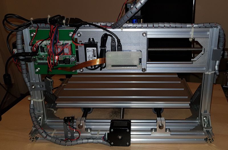
It’s probably clear to a Hackaday reader that we live in a golden era for hobbyist tool accessibility. Cheap single board computers can be bought at any neighborhood RadioShack or Maplin. 3D printers sell fully assembled and ready to run for less than $200. Even the humble CNC mill has come down the price curve, though as you might expect at the low end things can get pretty rough. Like a cheap 3D printer, a cheap mill tends to be missing some basic features you’d expect any reasonable machine to have. If you get your hands on one of these little wonders, [Shahada Abubakar] has a pair of great blog posts on the basic set of upgrades you’ll probably want to perform right out of the box.

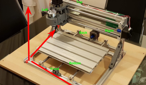
Which cheap CNC mills are we talking about? They go by a few names. Last year our own [Kristina Panos] put together a review of a shockingly inexpensive “1610” type sold by Linksprite (go take a read if you’re already considering a purchase!). The “1610” class, so named for it’s 16 cm x 10 cm bed size, is pretty common under a wide variety of manufacturer names. You can find them in this size made of 8020 like [Kristina] did or as “upgraded” versions cut from 1/4″ mystery plastic (often referred to in the listings as Bakelite, but your guess is as good as ours as to the true material). 1610 is the smallest size but basically the same machine exists as an 1810, 2418, or 3018. Each has a 775 size spindle and a single PCBA that handles stepper drive and runs grbl.

So what’s the problem? Well for one none of these machines have limit switches, though the controllers support them. [Shahada]’s guide has handy instructions for what kind to buy, how to wire them, and where they can be attached. Plus an overview of the G-code instructions to send the controller in order to home and configure everything properly. The controllers also like to be driven continuously over serial (though some sellers seem to offer a separate board to drive them). This is fine if you have a computer handy, but like a 3D printer it can be nice to bolt a Pi Zero or similar onto the unit and control it over the network. [Shahada]’s second post has a link to a mounting plate you can print for exactly that setup, as well as some suggestions for configuring CNC.js to drive everything.

Do you have one of these machines? Done any upgrades? Tell us in the comments! We’re always looking for ways to upgrade our home shop.

Byte Sized Pieces Help The KiCad Go Down

It’s no surprise that we here at Hackaday are big fans of Fritzing KiCad. But to a beginner (or a seasoned veteran!) the learning curve can be cliff-like in its severity. In 2016 we published a piece linking to project by friend-of-the-Hackaday [Chris Gammell] called Contextual Electronics, his project to produce formalized KiCad training. Since then the premier “Getting to Blinky” video series has become an easy recommendation for anyone looking to get started with Libre EDA. After a bit of a hiatus [Chris] is back with bite sized videos exploring every corner of the KiCad-o-verse.

A Happy [Chris] comes free with every video
The original Getting to Blinky series is a set of 10 videos up to 30 minutes long that walks through everything from setting up the the KiCad interface through soldering together some perfect purple PCBs. They’re exhaustive in coverage and a great learning resource, but it’s mentally and logistically difficult to sit down and watch hours of content. Lately [Chris] has taken a new tack by producing shorter 5 to 10 minute snapshots of individual KiCad features and capabilities. We’ve enjoyed the ensuing wave of learning in our Youtube recommendations ever since!

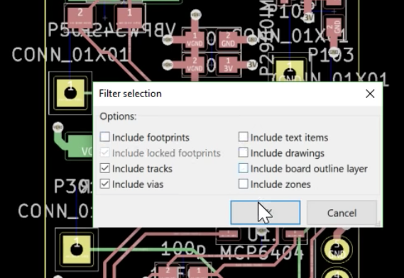
Selecting traces to rip up

Some of the videos seem simple but are extremely useful. Like this one on finding those final disconnected connections in the ratsnest. Not quite coverage of a major new feature, but a topic near and dear to any layout engineer’s heart. Here’s another great tip about pulling reference images into your schematics to make life easier. A fantastic wrapped up in a tidy three minute video. How many ways do you think you can move parts and measure distances in the layout editor? Chris covers a bunch we hadn’t seen before, even after years using KiCad! We learned just as much in his coverage of how to rip up routed tracks. You get the idea.

We could summarize the Youtube channel, but we aren’t paid by the character. Head on down to the channel and find something to learn. Make sure to send [Chris] tips on content you want him to produce!