Bathroom Scale

Reverse Engineering A Bathroom Scale For Automated Weight Tracking

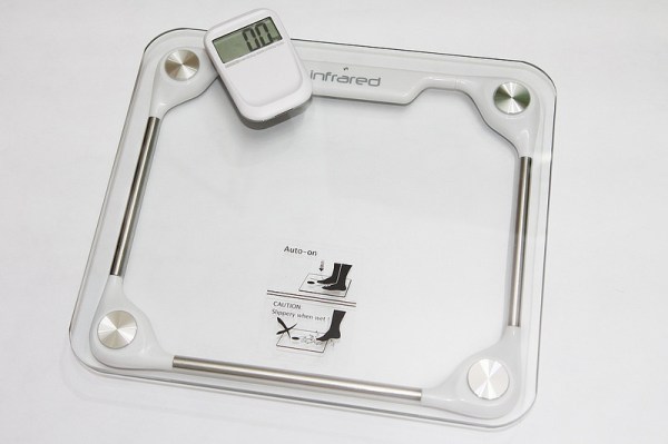
[Darell] recently purchased a fancy new bathroom scale. Unlike an average bathroom scale, this one came with a wireless digital display. The user stands on the scale and the base unit transmits the weight measurement to the display using infrared signals. The idea is that you can place the display in front of your face instead of having to look down at your feet. [Darell] realized that his experience with infrared communication would likely enable him to hack this bathroom scale to automatically track his weight to a spreadsheet stored online.

[Darell] started by hooking up a 38khz infrared receiver unit to a logic analyzer. Then he recorded the one-way communication from the scale to the display. His experience told him that the scale was likely using pulse distance coding to encode the data. The scale would start each bit with a 500ms pulse. Then it would follow-up with either another 500ms pulse, or a 1000ms pulse. Each combination represented either a 1 or a 0. The problem was, [Darell] didn’t know which was which. He also wasn’t sure in which order the bits were being transmitted. He modified a software plugin for his logic analyzer to display 1’s and 0’s on top of the waveform. He then made several configurable options so he could try the various representations of the data.

Next it was time to generate some known data. He put increasing amounts of weight on the scale and recorded the resulting data along with the actual reading on the display. Then he tried various combinations of display settings until he got what appeared to be hexadecimal numbers increasing in size. Then by comparing values, he was able to determine what each of the five bytes represented. He was even able to reconstruct the checksum function used to generate the checksum byte.

Finally, [Darell] used a Raspberry Pi to hook the scale up to the cloud. He wrote a Python script to monitor an infrared receiver for the appropriate data. The script also verifies the checksum to ensure the data is not corrupted. [Darell] added a small LED light to indicate when the reading has been saved to the Google Docs spreadsheet, so he can be sure his weight is being recorded properly.

Gesture Controlled Quadcopter

Controlling A Quadcopter With Gestures

[grassjelly] has been hard at work building a wearable device that uses gestures to control quadcopter motion. The goal of the project is to design a controller that allows the user to intuitively control the motion of a quadcopter. Based on the demonstration video below, we’d say they hit the nail on the head. The controller runs off an Arduino Pro Mini-5v powered by two small coin cell batteries. It contains an accelerometer and an ultrasonic distance sensor.

The controller allows the quadcopter to mimic the orientation of the user’s hand. The user holds their hand out in front of them, parallel to the floor. When the hand is tilted in any direction, the quadcopter copies the motion and will tilt the same way. The amount of pitch and roll is limited by software, likely preventing the user from over-correcting and crashing the machine. The user can also raise or lower their hand to control the altitude of the copter.

[grassjelly] has made all of the code and schematics available via github.

Home Automation

Home Automation With A Custom Wireless Sensor Network

We’re no strangers to home automation projects around here, but it’s not often that you see one described in this much detail. [Paul] designed a custom home automation system with four teammates for an undergraduate thesis project.

The system is broken into two main components; the server and the peripherals. The team designed their peripherals from early prototypes of an upcoming ArduIMU v4 measurement unit. They removed all of the default sensors to keep costs down and reduce assembly time. The units can them be hooked up to various peripherals such as temperature sensors, mains relays, RGB color strips, etc.

The central management of the system is performed using a web-based user interface. The web server runs on Java, and interacts with the peripherals wirelessly. Basic messages can be sent back and forth to either read the state of the peripherals or to change the state. As far as the user is concerned, these messages appear as simple triggers and actions. This makes it very simple to program the peripherals using if, then, else logic.

The main project page is a very brief summary of what appears to be a very well documented project. The team has made available their 182 page final report (pdf), which goes into the nitty-gritty details of the project. Also, be sure to watch the demonstration video below. Continue reading “Home Automation With A Custom Wireless Sensor Network”

DIY Optoisolator

MacGyvered Optoisolator Is A Great Introduction

Sometimes the best way to learn about a technology is to just build something yourself. That’s what [Dan] did with his DIY optoisolator. The purpose of an optoisolator is to allow two electrical systems to communicate with each other without being electrically connected. Many times this is done to prevent noise from one circuit from bleeding over into another.

[Dan] built his incredibly simple optoisolator using just a toilet paper tube, some aluminum foil, an LED, and a photo cell. The electrical components are mounted inside of the tube and the ends of the tube are sealed with foil. That’s all there is to it. To test the circuit, he configured an Arduino to send PWM signals to the LED inside the tube at various pulse widths. He then measured the resistance on the other side and graphed the resulting data. The result is a curve that shows the LED affects the sensor pretty drastically at first, but then gets less and less effective as the frequency of the signal increases.

[Dan] then had some more fun with his project by testing it on a simple temperature controller circuit. An Arduino reads a temperature sensor and if the temperature rises above a certain value, it turns on a fan to cool the sensor off again. [Dan] first graphed the sensor data with no fan hooked up. He only used ambient air to cool things down. The resulting graph is a pretty smooth curve. Next he hooked the fan up and tried again. This time the graph went all kinds of crazy. Every time the fan turned on, it created a bunch of electrical noise that prevented the Arduino from getting an accurate analog reading of the temperature sensor.

The third test was to remove the motor circuit and move it to its own bread board. The only thing connecting the Arduino circuit to the fan was a wire for the PWM signal and also a common ground. This smoothed out the graph but it was still a bit… lumpy. The final test was to isolate the fan circuit from the temperature sensor and see if it helped the situation. [Dan] hooked up his optoisolator and tried again. This time the graph was nice and smooth, just like the original graph.

While this technology is certainly not new or exciting, it’s always great to see someone learning by doing. What’s more is [Dan] has made all of his schematics and code readily available so others can try the same experiment and learn it for themselves.

Simple Photo Flash Trigger For Water Balloon Photography

Water Balloon Photography

There have been countless projects to make custom photo flash trigger circuits. Usually the circuits react to sound, triggering the camera flash at the moment a certain sound is triggered. That type of trigger can be used to detect the popping of a balloon or shattering of glass. Other triggers detect motion, like a projectile crossing a laser beam for example. [Udo’s] friend had a fun idea to take photos of water balloons popping. Unfortunately neither of those trigger methods would be well suited for this situation. That’s when [Udo] had to get creative.

[Udo] built a unique trigger circuit that uses the water inside the balloon as the trigger. The core component of the circuit is an Arduino. One of the Arduino’s analog pins is configured to enable the internal pull-up resistor. If nothing else is connected to the pin, the Arduino will read 5 volts there. The pin is connected to a needle on the end of a stick. There is a second needle on the same stick, just a short distance away from the first. When these needles pierce the balloon’s skin, the water inside allows for a brief moment of conductivity between the two pins. The voltage on the analog pin then drops slightly, and the Arduino can detect that the balloon has popped.

[Udo] already had a flash controller circuit. He was able to trigger it with the Arduino by simply trying the flash controller’s trigger pin to one of the Arduino’s pins. If the Arduino pulls the pin to ground, it closes the switch on the flash controller and the flash is triggered. Both circuits must share a common ground in order for this to work.

All of the code for [Udo’s] project is freely available. With such spectacular photographs, it’s only a matter of time before we see more of these floating around.

Strobe Remote

Reverse Engineering A Wireless Studio Lighting Remote

If you want to take a photograph with a professional look, proper lighting is going to be critical. [Richard] has been using a commercial lighting solution in his studio. His Lencarta UltraPro 300 studio strobes provide adequate lighting and also have the ability to have various settings adjusted remotely. A single remote can control different lights setting each to its own parameters. [Richard] likes to automate as much as possible in his studio, so he thought that maybe he would be able to reverse engineer the remote control so he can more easily control his lighting.

[Richard] started by opening up the remote and taking a look at the radio circuitry. He discovered the circuit uses a nRF24L01+ chip. He had previously picked up a couple of these on eBay, so his first thought was to just promiscuously snoop on the communications over the air. Unfortunately the chips can only listen in on up to six addresses at a time, and with a 40-bit address, this approach may have taken a while.

Not one to give up easily, [Richard] chose a new method of attack. First, he knew that the radio chip communicates to a master microcontroller via SPI. Second, he knew that the radio chip had no built-in memory. Therefore, the microcontroller must save the address in its own memory and then send it to the radio chip via the SPI bus. [Richard] figured if he could snoop on the SPI bus, he could find the address of the remote. With that information, he would be able to build another radio circuit to listen in over the air.

Using an Open Logic Sniffer, [Richard] was able to capture some of the SPI communications. Then, using the datasheet as a reference, he was able to isolate the communications that stored information int the radio chip’s address register. This same technique was used to decipher the radio channel. There was a bit more trial and error involved, as [Richard] later discovered that there were a few other important registers. He also discovered that the remote changed the address when actually transmitting data, so he had to update his receiver code to reflect this.

The receiver was built using another nRF24L01+ chip and an Arduino. Once the address and other registers were configured properly, [Richard’s] custom radio was able to pick up the radio commands being sent from the lighting remote. All [Richard] had to do at this point was press each button and record the communications data which resulted. The Arduino code for the receiver is available on the project page.

[Richard] took it an extra step and wrote his own library to talk to the flashes. He has made his library available on github for anyone who is interested.

Doorbell

A 1920’s Doorbell Is Upgraded With 2010’s Technology

When you move into an old house, you are bound to have some home repairs in your future. [Ben] discovered this after moving into his home, built in 1929. The house had a mail slot that was in pretty bad shape. The slot was rusted and stuck open, it was covered in old nasty caulk, and it had a built-in doorbell that was no longer functional. [Ben] took it upon himself to fix it up.

The first thing on the agenda was to fix the doorbell. After removing the old one, [Ben] was able to expose the original cloth-insulated wiring. He managed to trace the wires back to his basement and, to his surprise, they seemed to be functional. He replaced the old doorbell button with a new momentary button and then hooked up a DIY doorbell using an XBee radio. [Ben] already had an XBee base station for his Raspberry Pi, so he was wrote a script that could send a notification to his phone whenever the doorbell was pushed.

Unfortunately, the old wiring just didn’t hold up. The push button only worked sporadically. [Ben] ended up purchasing an off the shelf wireless doorbell. He didn’t want to have to stick the included ugly plastic button onto the front of his house though, so [Ben] had to figure out how to trigger the new doorbell using the nice metallic button. He used the macro lens on his iPhone to follow the traces on the PCB until he was able to locate the correct points to trigger the doorbell. Then it was just a matter of a quick soldering job and he had a functional doorbell.

Once the electronics upgrades were complete, he moved on to fixing up the look of the mail slot. He had to remove the rust using a wire brush and sandpaper. Then he gave it a few coats of paint. He replaced the original natural insulation with some spray foam, and removed all the old nasty caulk. The final product looks as good as new and now includes a functional wireless doorbell.

We’re big fans of salvaging old-school home hardware. Another example that comes to mind is this set of door chimes with modernized driver.