FCC Filing Reveals Tasty Hardware McSecrets

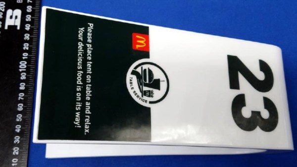
If you’ve visited a McDonald’s recently, you might have noticed something of a tonal shift. Rather than relying on angsty human teenagers to take customer orders, an increasing number of McDonald’s locations are now using self-serve kiosks. You walk up, enter your order on a giant touch screen, and then take an electronic marker with you to an open table. In mere minutes your tray of nutritious delicious cheap food is brought to you by… well that’s still probably going to be an angsty teenager.

Thanks to a recent FCC filing pointed out to us by an anonymous tipster, we now know what kind of tech Ronald has packed into the electronic table markers (referred to as “tents” in McDonald’s parlance). It turns out they are Bluetooth Low Energy beacons powered by the Nordic nRF52832 chipset, and include some unexpected features such as an accelerometer to detect falls.

The Nordic nRF52832 features a 32-bit ARM Cortex M4F processor at 64 MHz with 512 KB flash and 64 KB SRAM. Quite a bit of punch for a table marker. Incidentally, this is the same chip used in the Adafruit Feather nRF52 Pro, so there’s already an easily obtainable development toolchain.

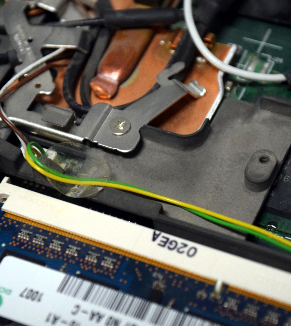
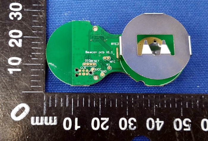
A image of the backside of the PCB shows a wealth of labeled test points, and we imagine figuring out how to get one of these table markers doing your own bidding wouldn’t be too difficult. Not that we condone you swiping one of these things along with your Quarter Pounder with Cheese. Though we are curious to know just why they need so much hardware to indicate which table to take a particular order to; it seems the number printed on the body of the device would be enough to do that.

This isn’t the first time we’ve taken a peek behind the Golden Arches. From reverse engineering their famous fries to hacking the toys they give out with Happy Meals, there’s more to do at the local McDonald’s than get thrown out of the ball pit again.

Hardware Store White Balance Reference

We live in a time in which taking pictures is preposterously easy: take out your phone (assuming it wasn’t already in your hands), point it at something, and tap the screen. The camera hardware and software in even basic smartphones today is good enough that you don’t need to give it much more thought than that to get decent pictures. But what if you want to do better than just decent?

Ideally you’d take photos lit by high temperature lights, but failing that, you might need to compensate by adjusting the white balance during post-processing. But to accurately adjust white balance you need a pure white reference point in the image. Thanks to some diligent research by the folks at the FastRawViewer blog, we now have a cheap and widely available source for a pure white reference material: PTFE pipe tape.

Alright, we know what you’re thinking: how hard could it be to find a white object? Well, if you’re talking about really white, it can actually be quite difficult. Take a walk down the paint aisle of your local hardware store and see just how many “whites” there actually are. Think the shirt your subject is wearing is really white? Think you can use the glossy white smartphone in their hand as a reference? Think again.

By taking a rubber eraser and wrapping it with a few layers of the PTFE tape, you can create a white reference that’s so cheap it’s effectively disposable. Which is good, because protecting your white reference object and keeping it clean can be a challenge in itself. But with a PTFE tape reference, you can just chuck the thing when the photo shoot is done.

Combine this cheap white reference with some of the DIY photography lighting setups we’ve covered in the past, and you’ll be well on the way to getting better images to document all your projects. Just remember to submit them to us when you’re done.

[Thanks to Keith Olson for the tip.]

Automated Turntable For 3D Scanning

Those just starting out in 3D printing often believe that their next major purchase after the printer will be a 3D scanner. If you’re going to get something that can print a three dimensional model, why not get something that can create said models from real-world objects? But the reality is that only a small percentage ever follow through with buying the scanner; primarily because they are notoriously expensive, but also because the scanned models often require a lot of cleanup work to be usable anyway.

While this project by [Travis Antoniello] won’t make it any easier to utilize scanned 3D models, it definitely makes them cheaper to acquire. So at least that’s half the battle. Consisting primarily of a stepper motor, an Arduino, and a EasyDriver controller, this is a project you might be able to assemble from the parts bin. Assuming you’ve got a pretty decent camera in there, anyway…

The general idea is to place a platform on the stepper motor, and have the Arduino rotate it 10 degrees at a time in front of a camera on a tripod. The camera is triggered by an IR LED on one of the Arduino’s digital pins, so that it takes a picture each time the platform rotates. There are configurable values to give the object time to settle down after rotation, and a delay to give the camera time to take the picture and get ready for the next one.

Once all the pictures have been taken, they are loaded into special software to perform what’s known as photogrammetry. By compiling all of the images together, the software is able to generate a fairly accurate 3D image. It might not have the resolution to make a 1:1 copy of a broken part, but it can help shave some modeling time when working with complex objects.

We’ve previously covered the use of photogrammetry to design 3D printed accessories, as well as a slightly different take on an automated turntable a few years ago. The process is still not too common, but the barriers to giving it a try on your own are at least getting lower.

Continue reading “Automated Turntable For 3D Scanning”

Texture Trick For 3D Prints From The Stone Age

Arguably one of the most difficult aspects of 3D printing is trying to make the finished product look like it wasn’t 3D printed. It can take a lot of time and work to cover up the telltale layer lines (or striations, if you want to get fancy), especially if your 3D printer isn’t perfectly calibrated. While there aren’t many shortcuts to achieve a glass-like finish on 3D printed parts, if your end goal is to make something that looks like stone, [Wekster] has a tip for you.

He demonstrates the technique by building a gorgeous recreation of the main gate from Jurassic Park. The process gives the relatively smooth plastic the gnarled look of rough-hewn stone with very little in the way of manual work. While it’s true there’s no overabundance of projects this stone-look finish will work for, it’s definitely something we’ll be filing away mentally.

So what’s the secret? [Wekster] first coats the 3D printed parts with common wood filler, the sort of stuff available at any hardware store. He then wraps them in clear plastic wrap, allowing the wrap to bunch up rather than trying to pull it taught. For extra detail, he digs into the plastic wrap here and there to create what will appear to be gaps and cracks on the finished piece. The wood filler is then left to dry; a process which normally only takes a few minutes, but now will take considerably longer as the plastic wrap will be keeping the air from it.

Once its hardened and unwrapped, [Wekster] sprays it with a base coat of color, and follows up with a few washings with watered down black and gray paints. This technique is well known to anyone who’s done miniature or model painting; serving to highlight the surface texture and give the finish more depth. With this method, anything that resembles a layer line in the print is long gone, and the surface looks so complex and detailed that at first glance few would believe it’s plastic.

[Wekster] also used wood filler during the finishing process for his Fallout 4 “Thirst Zapper” replica. In the past we’ve shown how you can smooth out 3D printed parts with epoxy and taken a very scientific look at using UV resin as a conformal coating, but maybe it’s time we give wood filler a shot.

Continue reading “Texture Trick For 3D Prints From The Stone Age”

What Will You Do If WWVB Goes Silent?

Buried on page 25 of the 2019 budget proposal for the National Institute of Standards and Technology (NIST), under the heading “Fundamental Measurement, Quantum Science, and Measurement Dissemination”, there’s a short entry that has caused plenty of debate and even a fair deal of anger among those in the amateur radio scene:

NIST will discontinue the dissemination of the U.S. time and frequency via the NIST radio stations in Hawaii and Ft. Collins, CO. These radio stations transmit signals that are used to synchronize consumer electronic products like wall clocks, clock radios, and wristwatches, and may be used in other applications like appliances, cameras, and irrigation controllers.

The NIST stations in Hawaii and Colorado are the home of WWV, WWVH, and WWVB. The oldest of these stations, WWV, has been broadcasting in some form or another since 1920; making it the longest continually operating radio station in the United States. Yet in order to save approximately $6.3 million, these time and frequency standard stations are potentially on the chopping block.

What does that mean for those who don’t live and breathe radio? The loss of WWV and WWVH is probably a non-event for anyone outside of the amateur radio world. In fact, most people probably don’t know they even exist. Today they’re primarily used as frequency standards for calibration purposes, but in recent years have been largely supplanted by low-cost oscillators.

But WWVB on the other hand is used by millions of Americans every day. By NIST’s own estimates, over 50 million timepieces of some form or another automatically synchronize their time using the digital signal that’s been broadcast since 1963. Therein lies the debate: many simply don’t believe that NIST is going to shut down a service that’s still actively being used by so many average Americans.

The problem lies with the ambiguity of the statement. That the older and largely obsolete stations will be shuttered is really no surprise, but because the NIST budget doesn’t specifically state whether or not the more modern WWVB is also included, there’s room for interpretation. Especially since WWVB and WWV are both broadcast from Ft. Collins, Colorado.

What say the good readers of Hackaday? Do you think NIST is going to take down the relatively popular WWVB? Are you still using devices that sync to WWVB, or have they all moved over to pulling their time down over the Internet? If WWVB does go off the air, are you prepared to setup your own pirate time station?

[Thanks to AG6QR for the tip.]

Simple ESP8266 Weather Station Using Blynk

Today’s hacker finds themself in a very interesting moment in time. The availability of powerful microcontrollers and standardized sensor modules is such that assembling the hardware for something like an Internet-connected environmental monitor is about as complex as building with LEGO. Hardware has become elementary in many cases, leaving software as the weak link. It’s easy to build the sensor node to collect the data, but how do you display it in a useful and appealing way?

This simple indoor temperature and humidity sensor put together by [Shyam Ravi] shows one possible solution to the problem using Blynk. In the video after the break, he first walks you through wiring the demonstration hardware, and then moves on to creating the Blynk interface. While it might not be the ideal solution for all applications, it does show you how quickly you can go from a handful of components on the bench to displaying useful data.

In addition to the NodeMCU board, [Shyam] adds a DHT11 sensor and SSD1306 OLED display. He’s provided a wiring diagram in the repository along with the Arduino code for the ESP8266, but the hardware side of this demonstration really isn’t that important. You could omit the OLED or switch over to something like a BME280 sensor if you wanted to. The real trick is in the software.

For readers who haven’t played with it before, Blynk is a service that allows you to create GUIs to interact with microcontrollers from anywhere in the world. The code provided by [Shyam] reads the humidity and temperature data from the DHT11 sensor, and “writes” it to the Blynk service. From within the application, you can then visualize that data in a number of ways using the simple drag-and-drop interface.

We’ve seen Blynk and ESP8266 used to control everything from mood lighting to clearance-rack robotic toys. It’s a powerful combination, and something to keep in mind next time you need to knock something together in short order.

Continue reading “Simple ESP8266 Weather Station Using Blynk”

Installing LibreBoot The (Very) Lazy Way

Recently I was given a somewhat crusty looking ThinkPad T400 that seemed like it would make a good knock around machine to have on the bench, if it wasn’t for the fact the person who gave it to me had forgotten (or perhaps never knew) the BIOS password. Cleaning the machine up, putting more RAM in it, and swapping the wheezing hard drive for an SSD would be a relatively cheap way to wring a few more years of life from the machine, but not if I couldn’t change the boot order in BIOS.

Alright, that’s not entirely true. I could have installed an OS on the SSD from my desktop and then put it into the T400, but there was something else at play. The locked BIOS gave me the perfect excuse to install LibreBoot on it, which is one of those projects I’ve had in the back of my mind for years now. Replacing the BIOS with something entirely different would solve the password issue, but there was only one problem: the instructions for flashing LibreBoot onto the T400 are intimidating to say the least.

You’re supposed to take the entire machine apart, down to pulling the CPU cooler off and removing the display. All so you can flip the motherboard over to access a flash chip between the CPU and RAM that’s normally covered by a piece of the laptop’s frame. Oh how I hated that diabolical chunk of magnesium which kept me from my silicon quarry. Flashing the chip would take a few minutes, but YouTube videos and first hand accounts from forums told me it could take hours to disassemble the computer and then put it back together after the fact.

Deep into that darkness I peered, long I stood there, wondering, fearing, doubting. Then a thought came to me: maybe I could just cut the thing. If it was a success, it would save me hours of work. If it failed, well, at least the computer didn’t cost me anything. Time to roll the dice.

Continue reading “Installing LibreBoot The (Very) Lazy Way”