Long PCB Shows Effects Of Ludicrous Speed

Transmission lines can seem like magic. When you make use of them it seems strange that a piece of wire can block or pass certain frequencies. It is less common to use transmission lines with pulses and typically your circuit’s transmission line behavior isn’t all that significant. That is, until you have to move a signal a relatively long distance. [Robert Baruch] has been using a long PCB to test pulse behavior on a bus he’s working on. He actually has a few videos in this series that are worth watching.

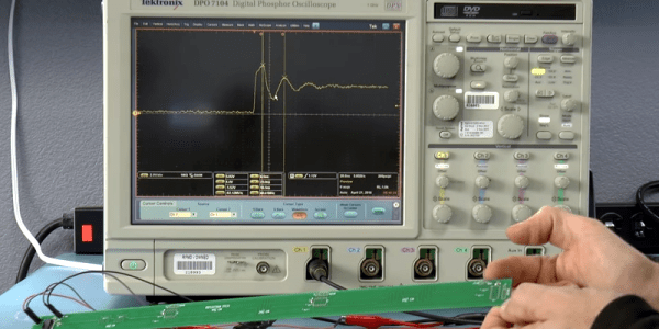
What makes it interesting is that [Robert] has enough distance on the board to where light-speed effects show up. By using a very nice DPO7104 oscilloscope and a signal generator, he shows how the signal reflects on the line at various points, adding and subtracting from it. The measurements matched theory fairly closely. You shouldn’t expect them to match exactly because of small effects that occur randomly throughout the system.

Continue reading “Long PCB Shows Effects Of Ludicrous Speed”

Dark Field Microscopy On The Cheap With A PCB

It might seem like a paradox that you want a dark field to see things with an expensive microscope. As [IMSAI Guy] explains, a dark field microscope doesn’t make the subject dark. It makes the area surrounding the subject dark. After selling his expensive microscope, he found he missed having the capability, so he decided to make one cheaply. You can see how he did it in the video, below.

Dark field microscopy gives better contrast and resolution by discarding light that shines directly through or reflects directly from a sample. The only light you see is any that scatters. If you think about a normal microscope, you can imagine a cone of light coming from the top or the bottom. The tip of the cone hits the sample and then spreads back out into another cone of light. What hits your eye –well, actually, the eyepiece — is all the light from that cone. In a dark field instrument, the illumination cone is hollow — the light is just a ring. That means any light the sample doesn’t scatter gets blocked by a stop in the objective. When there is no sample, there’s no unblocked light, so you see a “dark field.”

Light that either refracts through the sample (from below) or bounces off a feature (from the top) will wind up in the hollow area that passes through the objective and you’ll see the image. It may surprise you that you may already have a piece of dark field technology on your desk. Optical computer mice that can work on glass surfaces use this same technique. If you want to see some examples and a diagram of how it all works, we did a post on a similar lower tech mod. There’s also Wikipedia.

The secret to doing this cheaply was to get a used dark field objective with a little rust on the barrel and then modify them with a custom PC board to create an LED ring light. This is different from the usual illuminator which shines a light through a patch stop to block the inner light. In this case, the light is made into a ring shape by virtue of the arrangement of the LEDs.

Continue reading “Dark Field Microscopy On The Cheap With A PCB”

MSDOS Development With GCC

It might seem odd to think about programming in MSDOS in 2018. But if you are vintage computer enthusiast or have to support some old piece of equipment with an MSDOS single board computer, it could be just the thing. The problem is, where do you get a working compiler that doesn’t have to run on the ancient DOS machine? Turns out, gcc can do the trick. [RenéRebe] offers a video demo based on a blog post by [Chris Wellons]. You can see the video, below.

The technique generates COM files, not EXE files, so there are some limitations, such as a 64K file size. The compiler also won’t generate code for any CPU lower than a 80386, so if you have a real 8086, 80186, or 80286 CPU, you are out of luck. The resulting code will run in a real DOS environment on a ‘386 or higher or in a simulator like DOSBox.

You might be thinking why not use the DJGPP port of gcc to DOS. That sounds good, but it actually doesn’t produce true DOS code. It produces code for a DOS extender. In addition, [Chris] had trouble getting it to work with a modern setup.

The only real trick here is using the right combination of gcc flags to create a standalone image with the right codes. A COM file is just a dump of memory, so you don’t need a fancy header or anything. You also, of course, won’t have any library support, so you’ll have to write everything including functions to, say, print on the screen. Of course, you can borrow [Chris’] if you like.

The last pieces of the puzzle include adding a small stub to set up and call main and getting the linker to output a minimal file. Once you have that, you are ready to program like it is 1993. Don’t miss part 2, which covers interrupts.

If you pine away for QuickBasic instead of C, go download this. If you just want to run some old DOS games, that’s as close as your browser.

Continue reading “MSDOS Development With GCC”

Shirt Pocket Slide Rule: History Of The HP-35

In a recently updated post, [Codex99] has a detailed history of the HP-35 pocket calculator. Unless you are a certain age, you probably don’t think much of calculators. They are cheap and not very essential in this day of cell phones and PCs. But in the 1970s they were amazing technology and the desire of every engineer and engineering student.

The story opens in 1965 when Tom Osborne — who was not an HP employee — build a floating point calculator he called the Green Machine. Apparently, he had painted the balsa wood case green. He had been showing it around but failed to get any interest until he showed it to Bill Hewlett. Hewlett wanted it to do trig functions and offered him a six-week consulting gig to work on improvements.

HP engineer Dave Cochran helped out and also helped envision making the device keystroke-programmable. By 1968, this collaboration led to a 40-pound desktop calculator — the HP 9100 — that was the size of a typewriter. It could be yours for only $4900. Keep in mind, that same amount would buy two brand new cars in 1968.

Continue reading “Shirt Pocket Slide Rule: History Of The HP-35”

3D Printing Air Quality Study

You’ll often hear about some study in the media and then — on examination — find it doesn’t really apply to your situation. Sure, substance X causes cancer in rats, but they ate 8 pounds of it a day for a decade. That’s why we were glad to see [Chuck] post a series of videos about 3D printing air quality based on his practical experience. You can see the summary video, below.

[Chuck] is quick to point out that he isn’t a doctor or even a chemist. He also admits the $100 meter from IGERESS he is using isn’t necessarily high-quality test gear. Still, the data is a good guideline and he did get repeatable results.

Continue reading “3D Printing Air Quality Study”

Sign Of The Smith Chart Times

The Smith chart is a staple for analyzing complex impedance. [W2AEW] notes that a lot of inexpensive test gear like the MFJ-259B gives you complex readings, but fails to provide the sign of the imaginary part of the complex number. That makes it difficult to plot the results on a Smith chart or carry out other analysis. As you might expect, though, he has a solution for you that you can see in the video, below.

A common method is to increase the frequency slightly. In a simple case, you’d expect the imaginary part — the reactance — to go down for a capacitive impedance and up for an inductive one. Unfortunately, this doesn’t apply in many common cases, including when you are measuring through a transmission line which is probably what most people are doing with this type of test gear.

Continue reading “Sign Of The Smith Chart Times”

A Two-Range OLED Capacitance Meter

If you are just starting out in electronics, you need tools. But it is hard to build all your tools. Even though we see a lot of soldering station builds, you really ought to have a soldering iron to build the station. It is hard to troubleshoot a multimeter you just built if you don’t have a multimeter. However, a capacitance meter is a handy piece of gear, relatively simple to build, and you should be able to get it working without an existing capacitance meter. [gavinlyonsrepo] presents a simple design using an Arduino, an OLED display, and a few components.

The principle of operation is classic. On one range, the Arduino charges the capacitor through one resistor and discharges it through another while timing the operation. The amount of time taken corresponds to the capacitance.

Continue reading “A Two-Range OLED Capacitance Meter”