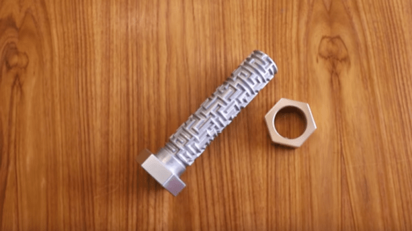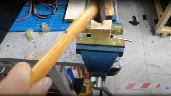
Resin printing still seems to polarize opinions amongst hacker types, with some considering such machines a good tool for the right tasks, and some just plain rejecting them outright. There are many arguments for and against, but like fused deposition modeling (FDM) machines, resin printers are improving in leaps and bounds — and so is the liquid resin itself. Nowadays low-odor resins are common, colors and finishes are varied, and now thanks to some dedicated development work, the brittleness that often characterizes such prints it being addressed. [Mayer Makes] has designed a super tough “engineering resin” that he demonstrates is so tough, you can print a nail and hammer it into a block of wood! (Video, embedded below, if you don’t believe it.)
This particular resin is destined for mixing, given its natural cured shade is a kind of greenish-grey, but it does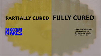 have a neat trick of presenting a definite yellowish hue when not fully cured, which is very helpful. This is particularly useful when removing support structures as you can use the color change during the curing process to judge the right moment to snap off the thicker sections, minimizing the risk of damaging the print. The resulting printed part is also tough enough to withstand subsequent traditional post-processing, such as milling, giving greater final finishing tolerances. Try doing that with an FDM print.
One of the neat things about resin chemistry is that you can simply mix them in their liquid form to tune the resin properties yourself and they can also be colored with specially formulated dyes without affecting the other properties too much, so this new super-tough resin gives prototypers yet another tool in their resin armory.
Thinking of taking the plunge and giving resin printing a try? Checkout our handy guide which may give you a leg up! If that doesn’t swing it for you, you could always use resin to help smooth out your FDM prints. It’ll probably still smell funny, mind.
Continue reading “Super Tough Resin Is Literally As Tough As Nails”