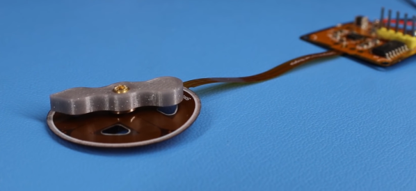
If you aren’t up to date with [Carl Bugeja]’s work with tiny brushless PCB motors, his summary video of his latest design and all the challenges it involved is an excellent overview.
Back in 2018 we saw [Carl]’s earliest versions making their first spins and it was clear he was onto something. Since then they have only improved, but improvement takes both effort and money. Not only does everything seemingly matter at such a small scale, but not every problem is even obvious in the first place. Luckily, [Carl] has both the determination and knowledge to refine things.
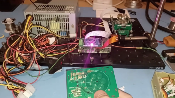
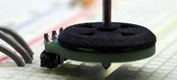
The end result of all the work is evident in his most recent test bed: an array of twenty test motors all running continuously at a constant speed of about 37,000 RPM. After a month of this, [Carl] disassembled and inspected each unit. Each motor made over 53 million rotations per day, closing out the month at over 1.6 billion spins. Finding no sign of internal scratches or other damage, [Carl] is pretty happy with the results.
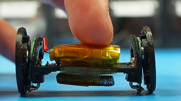
These motors are very capable but are also limited to low torque due to their design, so a big part of things is [Carl] exploring and testing different possible applications. A few fun ones include a wrist-mounted disc launcher modeled after a Spider-Man web shooter, the motive force for some kinetic art, a vibration motor, and more. [Carl] encourages anyone interested to test out application ideas of their own. Even powering a micro drone is on the table, but will require either pushing more current or more voltage, both of which [Carl] plans to explore next.
Getting any ideas? [Carl] offers the MotorCell for sale to help recover R&D costs but of course the design is also open source. The GitHub repository contains code and design details, so go ahead and make them yourself. Or better yet, integrate one directly into your next PCB.
Got an idea for an application that would fit a motor like this? Don’t keep it to yourself, share in the comments.
Continue reading “PCB Motor Holds Fast, Even After 1.6 Billion Spins”