Single Flex PCB Folds Into A Four-Wheel Rover, Complete With Motors

You’ve got to hand it to [Carl Bugeja] — he comes up with some of the most interesting electromechanical designs we’ve seen. His latest project is right up there, too: a single PCB that folds up into a four-wheel motorized rover.

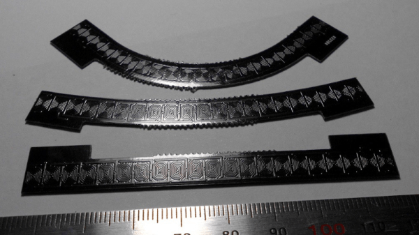
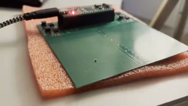
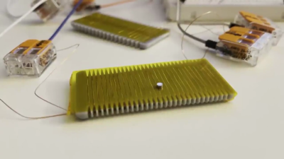
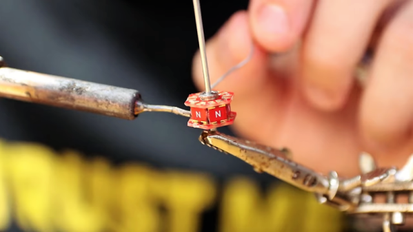
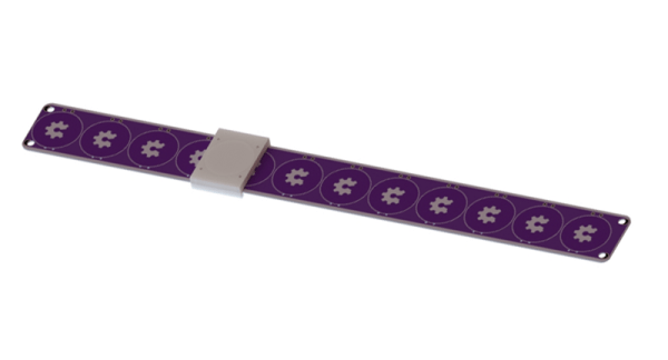
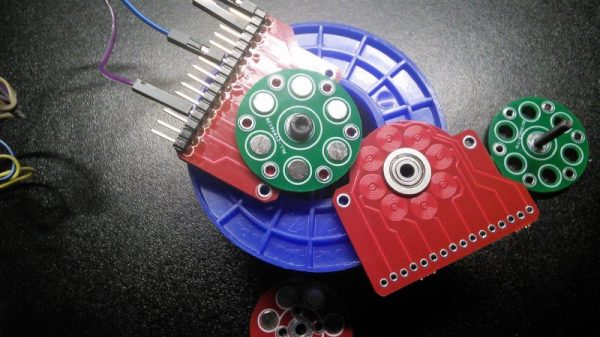
The key to [Carl]’s design lies with his PCB brushless motors, which he has been refining since we first spotted them back in 2018. The idea is to use traces on the PCB for the stator coils to drive a 3D printed rotor containing tiny magnets. They work surprisingly well, even if they don’t generate a huge amount of torque. [Carl]’s flexible PCB design, which incorporates metal stiffeners, is a bit like an unfolded cardboard box, with two pairs of motor coils on each of the side panels. This leaves the other surfaces available for all the electronics, with includes a PIC, a driver chip, and a Hall sensor for each motor, an IMU and proximity sensor for navigation, and an ESP32 to run the show.

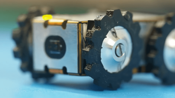
With machined aluminum rotors and TPU tires mounted to the folded-up chassis, it was off to the races, albeit slowly. The lack of torque from the motors and the light weight of the rover, along with some unwanted friction due to ill-fitting joints, added up to slow progress, especially on anything other than a dead flat surface. But with some tweaking, [Carl] was able to get the buggy working well enough to call this one a win. Check out the build and testing in the video below.

Knowing [Carl], this isn’t the last we’ll see of the foldable rover. After all, he stuck with his two-wheel PCB motor design and eventually got that running pretty well. We’ll be keeping an eye out for progress on this one.

Continue reading “Single Flex PCB Folds Into A Four-Wheel Rover, Complete With Motors”

linear motor pcb model railroad track

PCB Linear Motors For Model Trains

Modeling a railroad is hard. Railroads are large, linear pieces of civil engineering. So many modelers are drawn to the smallest scale they can use. Recently a new scale, named T, at 1:450 has been pushing this barrier. But fitting a reliable mechanical drive mechanism and MCU board in a package this size is a challenge. In practice, even more of a problem is getting reliable electrical contact through a metal wheel on metal track (about the worst possible design for a contact).T scale electric locomotive held on a human finger

T always seemed to us a long way out on the bleeding edge. But all that may have changed. In a recent Hackaday.io writeup, author [Martin] describes a PCB technology based linear motor system to externally drive T scale locomotives.

The system uses 4mm planar coils. The underside of the PCB has another coil, so the effective pitch is 2mm. With microstepping, a step of 0.25mm is possible, and trains run smoothly. Current is 3-400mA. Continue reading “PCB Linear Motors For Model Trains”

PCB Stepper Motor Micro Robots

[Kevin Lynagh] is interested in tiny PCB stepper motors, and after reviewing the various projects and patents to-date, decided to give it a try himself. These are basically a stepper motor that’s been unrolled and made flat — traces on the PCB act as the coils and tiny magnetic “robots” act as the rotor.

If you want to try this concept yourself, [Kevin]’s post contains an excellent survey of prior art and projects, as well as exploring the theory behind how these things work. He has taken a deep dive in to the theory, deep enough to grasp what’s going on and to build some preliminary prototypes with a bit of confidence. First off was just a hand-wound flat coil as a proof-of-concept. Next was a PCB version that worked almost exactly as planned, although he confesses to burning out a motor driver circuit before stepping back and making some calculations.

We covered one such project back in 2014 and wrote about a Hackaday.io magnetic robot project from reader [bobricius] in 2018. Have you ever used this technology for anything besides a demonstration? Let us know in the comments below.

Thanks to [Adrian] for sending us the tip.

Jigsaw Motor Uses PCB Coils For Radial Flux

Electric motors are easy to make; remember those experiments with wire-wrapped nails? But what’s easy to make is often hard to engineer, and making a motor that’s small, light, and powerful can be difficult. [Carl Bugeja] however is not one to back down from a challenge, and his tiny “jigsaw” PCB motor is the latest result of his motor-building experiments.

We’re used to seeing brushless PCB motors from [Carl], but mainly of the axial-flux variety, wherein the stator coils are arranged so their magnetic lines of force are parallel to the motor’s shaft – his tiny PCB motors are a great example of this geometry. While those can be completely printed, they’re far from optimal. So, [Carl] started looking at ways to make a radial-flux PCB motor. His design has six six-layer PCB coils soldered perpendicular to a hexagonal end plate. The end plate has traces to connect the coils in a star configuration, and together with a matching top plate, they provide support for tiny bearings. The rotor meanwhile is a 3D-printed cube with press-fit neodymium magnets. Check out the build in the video below.

Connected to an ESC, the motor works decently, but not spectacularly. [Carl] admits that more tweaking is in order, and we have little doubt he’ll keep optimizing the design. We like the look of this, and we’re keen to see it improved.

Continue reading “Jigsaw Motor Uses PCB Coils For Radial Flux”

Friday Hack Chat: Motors Made Out Of PCBs

One of the most amazing technological advances found in this year’s Hackaday Prize is the careful application of copper traces turned into coils. We’ve seen this before for RFID tags and scanners, but we’ve never seen anything like what Carl is doing. He’s building brushless motors on PCBs.

All you need to build a brushless motor is a rotor loaded up with super powerful and very cheap magnets, and a few coils of wire. Now that PCBs are so cheap, the coils of wire are easily taken care of. A 3D printer and some eBay magnets finish off the rest. For this week’s Hack Chat, we’re talking with Carl about PCB motors.

Carl Bugeja is a 23-year old electronics engineer who is trying to design new robotics technology. His PCB Motor design won the Open Hardware Design Challenge and will be going to the Finals of the Hackaday Prize. This open-source PCB motor is a smaller, cheaper, and easier to assemble micro-brushless motor.

[Carl]’s main project, the PCB Motor is a stator that is printed on a 4-layer PCB board. The six stator poles are spiral traces wound in a star configuration. Although these coils produce less torque compared to an iron core stator, the motor is still suitable for high-speed applications. [Carl]’s been working on other PCB motor designs, like the Linear PCB motor which is a monorail on a PCB and the Flexible PCB actuator where the coils of wire are tucked inside Kapton.

During this Hack Chat, we’re going to be discussing:

  • The design and construction of brushless motors
  • How to drive these motors
  • PCB applications beyond standard circuitry
  • Building accessible robotics technology

You are, of course, encouraged to add your own questions to the discussion. You can do that by leaving a comment on the Hack Chat Event Page and we’ll put that in the queue for the Hack Chat discussion.join-hack-chat

Our Hack Chats are live community events on the Hackaday.io Hack Chat group messaging. This week is just like any other, and we’ll be gathering ’round our video terminals at noon, Pacific, on Friday, August 10th. Need a countdown timer? You wouldn’t if we switched to universal metric time.

Click that speech bubble to the right, and you’ll be taken directly to the Hack Chat group on Hackaday.io.

You don’t have to wait until Friday; join whenever you want and you can see what the community is talking about.

PCBs As Linear Motors

PCBs are exceptionally cheap now, and that means everyone gets to experiment with the careful application of copper traces on a fiberglass substrate. For his Hackaday Prize entry, [Carl] is putting coils on a PCB. What can you do with that? Build a motor, obviously. This isn’t any motor, though: it’s a linear motor. If you’ve ever wanted a maglev train on a PCB, this is the project for you.

This project is a slight extension of [Carl]’s other PCB motor project, the aptly named PCB Motor. For this project, [Carl] whipped up a small, circular PCB with a few very small coils embedded inside. With the addition of a bearing, a few 3D printed parts, and a few magnets, [Carl] was able to create a brushless motor that’s also a PCB. Is it powerful enough to use in a quadcopter? Probably not quite yet.

Like [Carl]’s earlier PCB motor, this linear PCB motor follows the same basic idea. The ‘track’, if you will, is simply a rectangular PCB loaded up with twelve coils, each of them using 5 mil space and trace, adding up to 140 turns. This is bigger than the coils used for the (circular) PCB motor, but that only means it can handle a bit more power.

As for the moving part of this motor, [Carl] is using a 3D printed slider with an N52 neodymium magnet embedded inside. All in all, it’s a simple device, but that’s not getting to the complexity of the drive circuit. We’re looking forward to the updates that will make this motor move, turning this into a great entry for The Hackaday Prize.

A Brushless Motor On A PCB, Made From PCB

At Hackaday, we really appreciate it when new projects build on projects we’ve featured in the past. It’s great to be able to track back and see what inspires people to pick up someone else’s work and bring it to the next level or take it down a totally new path.

This PCB brushless motor is a great example of the soft collaboration that makes the Hackaday community so powerful. [bobricius] says he was inspired by this tiny PCB BLDC when he came up with his design. His write-up is still sparse at this point, but it looks like his motor is going to be used to drive a small robot. As with his inspiration, this motor has the stator coils etched right into the base PCB. But there are some significant improvements, like increasing the stator coil count from six to eight, as well as increasing the overall size of the motor. [bobricius] has also done away with the 3D-printed rotor of the original, opting to fabricate his rotor from stacked PCBs with cutouts for 5-mm neodymium magnets. We like the idea of using the same material throughout the motor, and it also raises the potential for stacking a second stator on the other side of the rotor, which might help mechanically and electrically. Even still, the prototype seems to hold its own in the video below.

This is [bobricius]’ second entry in the 2018 Hackaday Prize so far, after his not-a-Nixie tube display. Have you entered anything yet? Get to it! Prizes, achievements, and glory await.

Continue reading “A Brushless Motor On A PCB, Made From PCB”