A Hacker’s Christmas Story

Twas the night before Christmas, and because I decided to make everyone’s presents myself this year, I’m still working like mad to get everything done before the big deadline. Why do I do this to myself? Well, partly because I enjoy the process.

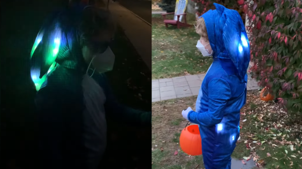
My wife had this idea that we can make the older folks some fun decorative blinky things, and picked some motives. My son then drew them out on paper, and I scanned those drawings in and traced them over in CAD. We then cut the shapes out of wood on the CNC router, which turned out to be incredibly successful. (Now that I’ve done it, I wouldn’t be surprised if all of those “quirky” decorative objects that the Swedish flat-packers sell aren’t initially sketched out by third graders.)

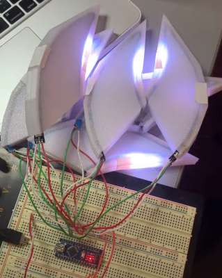
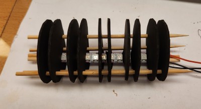
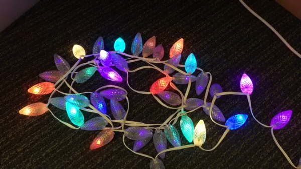
Then my son painted them, and it’s my job to insert the twinkling. I bought some of those three-wire “fairy lights” for the purpose, and they’re really fun to hack on. They’re like WS2812s, only instead of using four pins and shifting the data downstream, they’re on a bus, each with a hard-coded address – they know where they are in the string and each LED only listens for the Nth set of 24 bits. This means sending 200 color codes just to light up the 4 LEDs in Aunt Micki’s decorative tree, but so be it.

Last stop, and still to do as of the 23rd, route out some kind of wooden battery case, wedge in the LiPo and the charging circuits, and solder on an on/off switch. It’s down to the last minute, but isn’t that always the way?

Definitely would have been easier just to order something online. But is that the spirit of giving? No! The DIY way brings the family together, gets me some quality time with the CNC machine, and tones up my FreeCAD skills. My son even looked over my shoulder as we were coding some of the LED animations. And nothing says Christmas like hand-coded blinkies.

Happy Holidays, y’all!

LED Christmas Lights Optimized For Max Twinkleage

Old-school filament-based Christmas lights used to be available in twinkling form. LEDs, with their hard-on and hard-off nature, aren’t naturally predisposed to such behavior. To rectify this, some time ago, [Mark Kriegsman] built an Arduino program that makes LEDs twinkle beautifully.

The program is known as TwinkleFOX, and relies on the popular FastLED library for addressable LEDs. [Mark’s] demo setup is built around using WS2811 LEDs, put together in a string with plastic diffusers on each bulb. The Arduino is programmed to vary the brightness of each LED according to a triangle wave function. To create the twinkling effect, each LED has its own unique clock signal, so they vary in brightness at different times and at different rates.

Using an Arduino Uno or Leonardo, [Mark] reports its possible to twinkle 300 individual LEDs at a rate of over 50 updates a second. Using a faster microcontroller should net reliable performance with longer strings. Meanwhile, if you’re wondering how the older-style lights used to twinkle, we’ve covered that before too. Video after the break.

Continue reading “LED Christmas Lights Optimized For Max Twinkleage”

A two picture montage of a boy wearing a sonic the hedgehog costume with LEDs in them. The left picture is at night with the boy wearing sunglasses and a face mask with the sonic costume head piece lit up. The right picture is during the day with the boy wearing a face mask, holding a plastic pu mpkin bucket for candy and wearing a lit up sonic the hedgehog costume in the front yard of a house.

LEDs Put New Spin On A Sonic The Hedgehog Costume

[Wentworthm] couldn’t say no to his son’s plea for a Sonic the Hedgehog costume for Halloween but also couldn’t resist sprucing it up with LEDs either. The end result is a surprisingly cool light up Sonic the Hedgehog costume.

a picture of a breadboard with an Arduino Nano on it, with wires going out to 3d printed tear dropped shapes that have LED strips in them, with some LED strips on.

After some experimentation, [Wentworthm] ordered two costumes and ended up mixing and matching the head piece of one with the body suit of the other. For the head, [Wentworthm] created six 3D printed “quills” that had slots for the WS2812B LED strips to slide into and diffuse out the sides, with each quill sliding into the folds of the Sonic head “spikes”. Sewn strips of cloth were used to house the LED strips that were placed down the sides of the costume. An additional 3D printed switch housing was created to allow for a more robust interface to the two push buttons to activate the LEDs. An Arduino Nano, soldered to a protoboard, was used to drive the LED strips with a USB battery pack powering the whole project.

[Wentworthm] goes into more detail about the trials and errors, so the post is definitely worth checking out for more detail on the build. Halloween is always a great source of cool costumes and we’ve featured some great ones before, like a light up crosswalk costume to making a giant Gameboy colour costume.

Video after the break!

Continue reading “LEDs Put New Spin On A Sonic The Hedgehog Costume”

"The Great Resistor" color code illumination project

The Great Resistor Embiggens The Smallest Value

With surface-mount components quickly becoming the norm, even for homebrew hardware, the resistor color-code can sometimes feel a bit old-hat. However, anybody who has ever tried to identify a random through-hole resistor from a pile of assorted values will know that it’s still a handy skill to have up your sleeve. With this in mind, [j] decided to super-size the color-code with “The Great Resistor”.

Resistor color code from Wikipedia with white background
How the resistor color-code bands work

At the heart of the project is an Arduino Nano clone and a potential divider that measures the resistance of the test resistor against a known fixed value. Using the 16-bit ADC, the range of measurable values is theoretically 0 Ω to 15 MΩ, but there are some remaining issues with electrical noise that currently limit the practical range to between 100 Ω and 2 MΩ.

[j] is measuring the supply voltage to help counteract the noise, but intends to move to an oversampling/averaging method to improve the results in the next iteration.

The measured value is shown on the OLED display at the front, and in resistor color-code on an enormous symbolic resistor lit by WS2812 RGB LEDs behind.

Inside view of the great resistor showing WS2812 LEDs and baffle plates
Inside The Great Resistor, the LEDs and baffle plates make the magic work

Precision aside, the project looks very impressive and we like the way the giant resistor has been constructed. It would look great at a science show or a demonstration. We’re sure that the noise issues can be ironed out, and we’d encourage any readers with experience in this area to offer [j] some tips in the comments below. There’s a video after the break of The Great Resistor being put through its paces!

If you want to know more about the history of the resistor color code bands, then we have you covered.  Alternatively, how about reading the color code directly with computer vision?

Continue reading “The Great Resistor Embiggens The Smallest Value”

Arduino hearing test device overview

DIY Arduino Hearing Test Device

Hearing loss is a common problem for many – especially those who may have attended too many loud concerts in their youth. [mircemk] had recently been for a hearing test, and noticed that the procedure was actually quite straightforward. Armed with this knowledge, he decided to build his own test system and document it for others to use.

audiogram showing the results of the arduino hearing test device
Resultant audiogram from the device showing each ear in a different color

By using an Arduino to produce tones of various stepped frequencies, and gradually increasing the volume until the test subject can detect the tone, it is possible to plot an audiogram of hearing threshold sensitivity.  Testing each ear individually allows a comparison between one side and the other.

[mircemk] has built a nice miniature cabinet that holds an 8×8 matrix of WS2812 addressable RGB LEDs.  A 128×64 pixel OLED display provides user instructions, and a rotary encoder with push-button serves as the user input.

Of course, this is not a calibrated professional piece of test equipment, and a lot will depend on the quality of the earpiece used.  However, as a way to check for gross hearing issues, and as an interesting experiment, it holds a lot of promise.

There is even an extension, including a Class D audio amplifier, that allows the use of bone-conduction earpieces to help narrow down the cause of hearing loss further.

There’s some more information on bone conduction here, and we’ve covered an intriguing optical stimulation cochlear implant, too.

Continue reading “DIY Arduino Hearing Test Device”

A picture of the JagerMachine consisting of rectangular, desktop sized drink serving machine with a wooden varnish, a 3.5 inch touchscreen on the front face on top and a cavity with a shot glass in it, lit up by blue leds, with liquid pouring into it.

Shoot An Email To Get A Shot

[_Pegor] wanted to create a shot pouring machine for their friends birthday. Unfortunately, the build wasn’t done in time, but at least the JagerMachine is finished now so that others can use it.

The JagerMachine has a peristaltic pump that moves liquid from a reservoir hidden in the back of the machine to the glass in front. The machine has a 3.5 inch DSI touch screen display for user input and a WS2812B LED ring for creating a small light show when the drinks are served. A 3.3 V to 5 V level shifter is used to power the LED ring and a motor driver module is used to drive the peristaltic pump motor. It looks like there’s a “shot glass detection” feature that uses a 3D printed mini platform with a notch for a magnet so that when a glass is placed on top of it, the hall sensor can detect the presence of the nearby magnet.

Part of the charm of this project is the software stack on the Raspberry Pi that allows for novel interaction, including being able to serve drinks from the receipt of emails. Using the Raspberry Pi as the controlling device allows for this rich set of interfacing options, including easily allowing the ability to drive the LEDs, detect the presence of the shot glass, along with establishing network connectivity. The setup procedures are all documented in the repository for anyone wanting to see how this type of functionality might transfer to their own project.

Drink mixing robots are, of course, a thing. ranging from small and cute to full shelf.

Two shots of a Thriller jacket with LED strips being worn by Louise Katzovitz, one from the front and the other from the back.

Thrills With An LED “Thriller” Jacket

[Louise Katzovitz] has created a light-up jacket in the style of the jacket worn by Michael Jackson in the 1983 music video for “Thriller”. [Louise Katzovitz]’s Thriller jacket is the perfect example of combining sewing hacks and electronic hacks to make an awesome, wearable jacket.

A bomber jacket was used as the base form to layer on the sequins and LED strips. Instead of bands of metal studs, [Louise] used WS2812B 60 pixels/m LED strips. 3D-printed transparent PLA “gems” were placed on top of the LEDs to mimic the form of the metal studs in the original jacket and provide diffusion for the underlying LEDs.

Inside of the LED thriller jacket, with battery pack, arduino nano and wiring exposed

Each LED strip was laid out on a piece of vinyl strip. Then, a top layer of vinyl was cut to allow each of the LEDs to poke through, with the 3D printed gems super-glued on top. The assembled LED bands are attached to the jacket by Velcro with the wiring fed behind the lining material, which can be removed easily via small hooks. The whole thing is driven by an Arduino Nano and a 5 V power bank.

With the details and process worked out, [Louise] even made a tiny version of the jacket for her dog. We’ve featured LED wearables and fashion before and [Louise]’s jacket is a great addition. These projects are perfect for anyone who wants to wow their friends this upcoming Halloween season. Video after the break!

Continue reading “Thrills With An LED “Thriller” Jacket”