Emulating Biology For Robots With Rolling Contact Joints

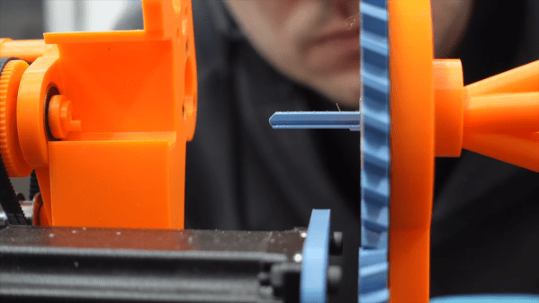
Joints are an essential part in robotics, especially those that try to emulate the motion of (human) animals. Unlike the average automaton, animals are not outfitted with bearings and similar types of joints, but rather rely sometimes on ball joints and a lot on rolling contact joints (RCJs). These RCJs have the advantage of being part of the skeletal structure, making them ideal for compact and small joints. This is the conclusion that [Breaking Taps] came to as well while designing the legs for a bird-like automaton.

These RCJs do not just have the surfaces which contact each other while rotating, but also provide the constraints for how far a particular joint is allowed to move, both in the forward and backward directions as well as sideways. In the case of the biological version these contact surfaces are also coated with a constantly renewing surface to prevent direct bone-on-bone contact. The use of RCJs is rather common in robotics, with the humanoid DRACO 3 platform as detailed in a 2023 research article by [Seung Hyeon Bang] and colleagues in Frontiers in Robotics and AI.

The other aspect of RCJs is that they have to be restrained with a compliant mechanism. In the video [Breaking Taps] uses fishing line for this, but many more options are available. The ‘best option’ also depends on the usage and forces which the specific joint will be subjected to. For further reading on the kinematics in robotics and kin, we covered the book Exact Constraint: Machine Design Using Kinematic Principles by [Douglass L. Blanding] a while ago.

Continue reading “Emulating Biology For Robots With Rolling Contact Joints”

This Robot Picks Locks, If You’re Very Patient

We all know the Hollywood trope of picking a lock with a paperclip, and while it certainly is doable, most reputable locks require slightly more sophisticated tools to pick effectively. That’s not to say that wire is off the table for locksports, though, as this cool lock-picking robot demonstrates.

The basics behind [Sparks and Code]’s design are pretty simple. Locks are picked by pushing pins up inside the cylinder until they line up with the shear plane, allowing the cylinder to turn. Normally this is done a pin at a time with a specialized tool and with a slight bit of torque on the cylinder. Here, tough, thin, stiff wires passing through tiny holes in a blade shaped to fit the keyway are used to push all the pins up at once, eliminating the need to keep tension on the cylinder to hold pins in place.

Sounds simple, but in practice, this looks like it was a nightmare. Getting five wires to fit into the keyway and guiding them to each pin wasn’t easy, nor was powering the linear actuators that slide the wires in and out. Applying torque to the lock was a chore too; even though tension isn’t needed to retain picked pins, the cylinder still needs to rotate, which means moving the whole picking assembly. But the biggest problem by far seems to be the fragility of the blade that goes into the keyway. SLA might not be the best choice here; perhaps the blade could be made from two thin pieces of aluminum with channels milled on their faces and then assembled face-to-face.

The robot works, albeit very slowly. This isn’t [Sparks and Code]’s first foray into robot lock picking. His previous version attempted to mimic how a human would pick a lock, so this is really thinking outside the box.

Continue reading “This Robot Picks Locks, If You’re Very Patient”

Source Code To The 1999 FPS Game Descent 3 Released

On April 16th of this year, [Kevin Bentley] released the source code to the Sci-Fi FPS game Descent 3. Originally released in 1999 for Windows, the game has you control a flying ship which you have to guide through both in- and outdoor environments, while shooting at robots that have been infected with an alien virus as you try to save the solar system. It was later also ported to Mac OS and Linux, but was considered a commercial flop due to low sales.

As one of the original developers, [Kevin] explains that one of the goals of this code release is to give the game a second life, by cleaning up the C++ code and using new APIs. Original proprietary audio and video libraries from Interplay were removed, which means that some work is required before one can build a fresh copy of the game from this code base. That said, the released code is the latest 1.5 patch level, with the Mac OS and Linux support. Even if the original Descent games weren’t your cup of tea, it’s still great to see games being preserved and updated like this.

Thanks to [Phil Ashby] for the tip.

Laser cut bug body with pincers and electronics to control the pincers

A Buggy Entry In The Useless Robot Category

No one loves a useless robot more than we do here at Hackaday. But if anyone does it might be [ARC385] with her Bug Bite Bot.

A true engineering marvel, [ARC385]’s bug bot extinguishes the candle on its own little birthday cupcake. Yup. That’s it! Even more peculiar, (and to be fair, somewhat fittingly) before her bug releases its less-than-crushing bite, it plays itself a little Happy Birthday jingle. Seems legit.

If you choose to build this little bug yourself, you’ll be happy to know that the electronics on this build are pretty straightforward. Servo motors control the pincers and a photoresistor detects the flame. [ARC385] tried using a flame sensor instead of the photoresistor, but mentioned she couldn’t get consistent performance at her required sensing distance. She also mentions that you’ll probably need to calibrate the photoresistor to ambient light if for whatever reason you choose to embark on this build yourself.

[ARC385] did a pretty good job with the laser-cut plywood to construct the bug, but using plywood adds a few more question marks to this already puzzling build. She even mentioned having to modify the pincers so they wouldn’t catch fire trying to extinguish the candle.

Would be cool if the candle could rekindle itself, but we can’t possibly support making this hack even more of a fire hazard than it already is.

Continue reading “A Buggy Entry In The Useless Robot Category”

Ultimate Power: Lithium-Ion Packs Need Some Extra Circuitry

A LiIon pack might just be exactly what you need for powering a device of yours. Whether it’s a laptop, or a robot, or a custom e-scooter, a CPAP machine, there’s likely a LiIon cell configuration that would work perfectly for your needs. Last time, we talked quite a bit about the parameters you should know about when working with existing LiIon packs or building a new one – configurations, voltage notations, capacity and internal resistance, and things to watch out for if you’re just itching to put some cells together.

Now, you might be at the edge your seat, wondering what kind of configuration do you need? What target voltage would be best for your task? What’s the physical arrangement of the pack that you can afford? What are the safety considerations? And, given those, what kind of electronics do you need?

Picking The Pack Configuration

Pack configurations are well described by XsYp:X serial stages, each stage having Y cells in parallel. It’s important that every stage is the same as all the others in as many parameters as possible – unbalanced stages will bring you trouble.

To get the pack’s nominal voltage, you multiply X (number of stages) by 3.7 V, because this is where your pack will spend most of its time. For example, a 3s pack will have 11.1 V nominal voltage. Check your cell’s datasheet – it tends to have all sorts of nice graphs, so you can calculate the nominal voltage more exactly for the kind of current you’d expect to draw. For instance, the specific cells I use in a device of mine, will spend most of their time at 3.5 V, so I need to adjust my voltage expectations to 10.5 V accordingly if I’m to stack a few of them together.

Now, where do you want to fit your pack? This will determine the voltage. If you want to quickly power a device that expects 12 V, the 10.5 V to 11.1 V of a 3s config should work wonders. If your device detects undervoltage at 10.5V, however, you might want to consider adding one more stage.

How much current do you want to draw? For the cells you are using, open their spec sheet yet again, take the max current draw per cell, derate it by like 50%, and see how many cells you need to add to match your current draw. Then, add parallel cells as needed to get the capacity you desire and fit the physical footprint you’re aiming for. Continue reading “Ultimate Power: Lithium-Ion Packs Need Some Extra Circuitry”

Rosie The Robot Runs For Real

On the recent 256th episode of the Hackaday podcast, [Kristina] mentioned her favorite fictional robot was Rosie from The Jetsons. [Robert Zollna] must agree since he built a reimagined Rosie and it even caught the notice of mainstream outlet People magazine.

We didn’t find much information outside of the TikTok video (see below; you can use the Guest button if you don’t have an account). However, there were a few clever ideas here. First, the robot mechanism is actually Rosie’s vacuum cleaner. Like a tail wagging a dog, an off-the-shelf floor vac tows the robot body.

Rosie herself is clearly an office chair base with an artistic body. The head rotates, and the mouth appears to open and close, so there’s apparently a little more electronics inside, but that’s nothing you couldn’t throw together with some RC servos and an ESP32.

Some videos cover the build so you might be able to glean more details, but the bite-sized videos aren’t very descriptive even though they are fun to watch. If you thought folks documenting their projects on YouTube was bad, you’re really gonna love the TikTok generation.

We like the look of Rosie, but as a practical matter, we need our robot vac to be smaller, not larger. However, using these off-the-shelf robots as a quick start for a robotics project is reasonable. Especially if you can pick up one cheap. Not that that’s a new idea. They even make stripped-down units with the intent that you don’t want to use them as cleaners.

Continue reading “Rosie The Robot Runs For Real”

The $16 PCB Robot

It is a fun project to build a simple robot but, often, the hardest part these days is creating the mechanical base. [Concrete Dog] has a new open source design for stoRPer that uses a PC board as the base. The board has a Raspberry Pi Pico and motor drivers. The modular design allows you to add to it easily and use custom wheels. The video below shows some treaded wheels and some mechanum wheels with gears.

There are mounting holes for sensors and also a way to put another deck above to hold other circuits, power, or whatever you like. There’s lots you could do with this as a starting point.

Continue reading “The $16 PCB Robot”