There are various ways to measure plant health, and we’ve seen many projects creating open-source solutions. One we haven’t seen is a dendrometer, which involves measuring various physical dimensions of trees to track their health and growth. [John Opsahl] is changing this with the OpenDendrometer, a tool for tracking the diameter of tree limbs and fruit.
Tiny changes in diameter take place throughout the day, and tracking these changes allows deviations to be detected, which can be a sign of water stress. Over weeks and months, these measurements can be used to measure growth and fruits’ progress to harvest. [John] found that a digital tire tread depth gauge can work well for this application. Many of these gauges use the same electronics as the cheap digital calipers, for which the serial protocol was reverse engineered more than a decade ago. The OpenDendrometer connects the tire depth gauge to a microcontroller via a 1.5V level shifter, which logs measurements to an SD card while using a DS3231 RTC for accurate timestamps. The RTC can also be used to wake up the circuit at the required intervals to save battery power. For the initial proof of concept [John] is using an Arduino Pro Mini, but plans to move to an ESP32 at a later stage to allow wireless data transmission.
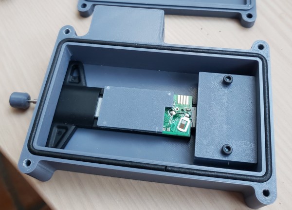
Everything will be housed in a 3D printed enclosure with a foam cord gasket to make the device weather resistant. A mounting rod on the outside of the enclosure with adjustable thumbscrews allows the OpenDendrometer to be attached to any part of the tree. We plan to keep an eye on this project and look forward to seeing the data it produces.
For the other ways of measuring plant health, we’ve covered everything from soil moisture to Normalized Difference Vegetation Index and even plant weight and even pot plant weight.