Teardown: Creality Wi-Fi Box

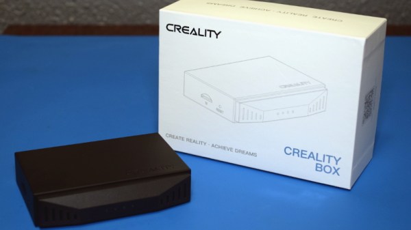
Creality, makers of the Ender series of 3D printers, have released a product called Wi-Fi Box meant to cheaply add network control to your printer. Naturally I had to order one so we could take a peek, but this is certainly not a product review. If you’re looking to control your 3D printer over the network, get yourself a Raspberry Pi and install Gina Häußge’s phenomenal OctoPrint on it. Despite what Creality might want you to believe, their product is little more than a poor imitation of this incredible open source project.

Even if you manage to get it working with your printer, which judging by early indications is a pretty big if, it won’t give you anywhere near the same experience. At best it’ll save you a few dollars compared to going the DIY route, but at the cost of missing out on the vibrant community of plugin developers that have helped establish OctoPrint as the defacto remote 3D printing solution.

That being said, the hardware itself seems pretty interesting. For just $20 USD you get a palm-sized Linux computer with WiFi, Ethernet, a micro SD slot, and a pair of USB ports; all wrapped up in a fairly rugged enclosure. There’s no video output, but that will hardly scare off the veteran penguin wrangler. Tucked in a corner and sipping down only a few watts, one can imagine plenty of tasks this little gadget would be well suited to. Perhaps it could act as a small MQTT broker for all your smart home devices, or a low-power remote weather station. The possibilities are nearly limitless, assuming we can get into the thing anyway.

So what’s inside the Creality Wi-Fi Box, and how hard will it be to bend it to our will? Let’s take one apart and find out.

Continue reading “Teardown: Creality Wi-Fi Box”

DIY ESP32 Video Doorbell Locks Out Big Brother

There’s no question that being able to see who’s at your front door from your computer or mobile device is convenient, which is why the market is currently flooded with video doorbells. Unfortunately, it’s not always clear who else has access to the images these devices capture. Organizations such as the Electronic Frontier Foundation have argued that by installing one of these Internet-connected cameras on their front door, consumers are unwittingly contributing to a mass surveillance system that could easily be turned against them.

Luckily, there’s a solution. As [Sebastian] shows in his latest project, you can build your own video doorbell that replicates the features of the commercial offerings while ensuring you’re the only one who has access to the data by leveraging open source, community developed projects such as ESPHome and Home Assistant. At the same time, modern manufacturing techniques like desktop 3D printing and low-cost PCB fabrication mean your DIY doorbell doesn’t have to look like you made it yourself.

The project starts with a custom PCB that combines the ESP32, a camera module, a capacitive touch sensor, a relay to optionally trigger an electronic door lock, and a DC-DC converter that will let you power the device from a wide range of input voltages. The board even has a spot where you can solder on an additional 8 MB of external PSRAM for the ESP32, which will enable the chip to capture higher resolution video.

The electronics are housed in a minimalistic 3D printed enclosure that would fit right in alongside similar gadgets from the likes of Ring and Arlo; especially if you have access to a CNC and can cut the front panel out of acrylic. The lighted touch sensor looks phenomenal, and really gives the device a professional feel. That said, it doesn’t look like the case would last very long if exposed to harsh weather and there are some obvious physical security issues with this approach. But to be fair, we’ve seen the same problem with commercial hardware.

Naturally with a project like this, the hardware is only half of the story. It takes a considerable amount of software poking and prodding to get things like mobile device notifications working, and as a special added annoyance, the process is different depending on which MegaCorp produced the OS your gadget is running. [Sebastian] has documented the bulk of the process in the video after the break, but the finer points will likely need some adjustment depending on how you want to set things up.

This is an exceptionally impressive project for sure, but if the whole slick futuristic look isn’t your style, you could always opt to go with the DIY video door bell that looks like it came from an alternate reality version of 1986.

Continue reading “DIY ESP32 Video Doorbell Locks Out Big Brother”

A Synth Of Your Own, For Not A Lot

Despite the lingering reality that most of us don’t have what it takes to make it to the upper reaches of the Hit Parade, there remain many who still harbour a secret desire to make music. What better way to realise this dream, than by making [Blog Hoskins’] $20 MIDI synth project!

The write-up goes into a staggering level of detail to ensure that it’s accessible at all levels, to the extent that a complete beginner could probably assemble a working synth by following it. For some of the fancier parts of front panel there’s a reliance on a laser cutter, but even without such wizardry the Average Joe with an electric drill could still do a pretty good job.

Behind the panel though it’s not short on features it’s a surprisingly simple design. At its heart is an Arduino Nano, surrounded by potentiometers and switches for user control, and an opto-coupler for the MIDI lines. Sadly for analogue synth fans there’s not much else in the way of circuitry, but the point of a build such as this one is to create a playable instrument with the shortest path to usability. A video full fo those glorious synth sounds is below the break.

MIDI synthesisers are a frequent feature here at Hackaday. A recent favourite is this four-voice instrument that uses servos as its active element.

Continue reading “A Synth Of Your Own, For Not A Lot”

Digispark Spoofs IR To Get Speakers Under Control

The Microlab 6C are a pretty nice pair of speakers, but [Michał Słomkowski] wasn’t too thrilled with the 8 watts they consume when on standby. The easy fix is to just unplug them when they aren’t in use, but unfortunately the digital controls on the front panel mean he’s got to turn them on, select the correct input, and turn the volume up to the appropriate level every time they’re plugged back in. Surely there must be a better way.

His solution was to use a Digispark to fire off the appropriate IR remote codes so they’d automatically be put back into a usable configuration. But rather than putting an IR LED on one of the GPIO pins, he simply spliced it into the wire leading back from the speaker’s IR receiver. All his code needs to do is generate the appropriate pulses on the line, and the speaker’s electronics think its a signal coming in from the remote.

Distinctive patterns on the IR sensor wires.

Power for the Digispark is pulled from the speaker itself, so it turns on once [Michał] plugs them back in. The code waits five seconds to make sure the hardware has had time to start up, then proceeds with the “Power On”, “Change Input”, and “Volume Up” commands with a few seconds in between each for good measure.

Not only was it easier to skip the IR and inject the signals directly, but it also made for a cleaner installation. Since the microcontroller doesn’t need line of sight to the IR receiver, [Michał] was able to hide it inside the speaker’s enclosure. From the outside, the modification is completely invisible.

We’ve seen similar code injection tricks used before, and it’s definitely one of those techniques you should file away mentally for future reference. Even though more and more modern devices are embracing WiFi and Bluetooth control, the old school IR remote doesn’t seem like it’s going away anytime soon.

Interactive Subway Map Talks You Through The Route

Old-school rail monitoring systems had amazing displays of stations and tracks covered in flashing lights that tracked the progress of trains along a route. While it’s unlikely you’ll fit such big iron from the mid-20th century in your home, you can get a similar aesthetic with [Kothe’s] interactive subway information display.

The display relies on an Arduino Mega 2560 Pro Mini as the brains of the operation. It drives strings of WS2812B LEDs which correspond to stations along the various metro lines in the area. Additionally, the microcontroller drives a 4.3″ Nextion LCD display. The Nextion displays have the benefit of acting as a self-contained human machine interface, running their own controller on board. This means the Arduino doesn’t have to spend cycles driving the display, and the Nextion hardware comes with a useful software package for quickly and easily designing GUI interfaces. For further feedback, a DFPlayer MP3 module is used to allow the system to playback prerecorded voice samples that provide information on the rail system. The attractive front panel is made with lasercut acrylic and a color printed acetate sheet.

It’s a build that bears striking similarity to real rail information systems fielded by railways around the world. We can imagine such a device being particularly useful in a backpacker’s hostel or university dorm to help those new to town find their way around. If you prefer a more stripped-back aesthetic, we’ve seen a barebones PCB build done as well. Video after the break.

Continue reading “Interactive Subway Map Talks You Through The Route”

Domino Clock Tells The Time In Style

It seems there are as many ways to display the time as there are ways to measure it in the first place. [Kothe] saw a fancy designer domino clock, and wanted a piece of the action without the high price tag. Thus, the natural solution was to go the DIY route.

An Arduino Nano is the heart of the build, paired with a DS1307 RTC for accurate timekeeping. The case of the clock consists of a 3D printed housing, fitted with layers of lasercut acrylic. Behind this, a smattering of WS2812B addressable LEDs are fitted, which shine through the translucent grey plastic of the front panel. This enables each LED to light up a dot of the domino, while remaining hidden when switched off. Reading the time is as simple as counting the dots on the dominoes. The first domino represents hours, from 1 to 12, while the second and third dominoes represent the minutes.

As a timepiece, the domino clock serves well as a stylish decor piece, and could also be a fun way to teach kids about electronics and telling the time. Makers do love a good timepiece, and our clock tag is always overflowing with fresh hacks on a regular basis. If you’ve got your own fancy build coming together at home, you know who to call!

Big Workshop Clock Is 3D Printing Done Right

Time is something uniquely important to humans, and they remain the only creatures on the planet to build devices to regularly track its progress. [Ivan Miranda] is one such creature, and built a giant 7-segment clock for his workshop that really ties the room together.

The clock is a testament to [Ivan]’s design skills in the 3D printed space. Taking advantage of his large format printer, each segment consists of a front panel, large single-piece diffuser, LED carrier, and backing plate. There are plenty of nice touches, from the interlocking ridges between each digit, to integral printed arrows on the inside that guide installation of the LED strips. Fit and finish approaches the level of a commercial product, a reward for [Ivan]’s years of practice in the field.

Electronically, an ESP8266 runs the show, synchronizing the time over its in-built WiFi connection. Each segment contains 9 WS2812B LEDs, wired up in a single long strip that’s addressed by the microcontroller. This means that the segments can be lit up to any color of the rainbow, though [Ivan] is a man who best appreciates the look of classic red.

[Ivan]’s long been a proponent of big 3D-printed builds — his tank-tracked electric skateboard is a particularly good example. Video after the break.

Continue reading “Big Workshop Clock Is 3D Printing Done Right”