If there’s one thing audiences love in sci-fi, it’s a cute robot companion that follows the heroes around. If you want one of your own, starting with this build from [mircemk] could be just the ticket.
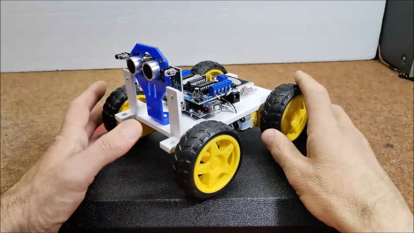
The build relies on the classic Arduino Uno microcontroller, which talks to a HC-SR04 ultrasonic sensor module and two infrared sensors in order to track a human target and follow it around. Drive is thanks to four DC gear motors, driven by a L293D motor driver, with a two-cell lithium battery providing power for everything onboard.
The robot works in a simple manner, following a hand placed in front of the robot’s sensors. First, the robot checks for the presence of an object in front using the ultrasonic sensor. If something is detected, the twin infrared sensors mounted left and right are used to guide the robot, following the hand.
It’s not a sophisticated algorithm, and it won’t really let your robot follow you down a crowded street. However, it’s a great project to learn on for beginners and could serve as a great entry into more advanced projects using face tracking or other techniques. Video after the break. Continue reading “2022 Sci-Fi Contest: A Hand-Following Robot, Powered By Arduino”