OBDII to Speed Pulse: Atmel ICE

Building An OBD Speed Pulse: Behold The ICE

I am a crappy software coder when it comes down to it. I didn’t pay attention when everything went object oriented and my roots were always assembly language and Real Time Operating Systems (RTOS) anyways.

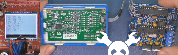
So it only natural that I would reach for a true In-Circuit-Emulator (ICE) to finish of my little OBDII bus to speed pulse generator widget. ICE is a hardware device used to debug embedded systems. It communicates with the microcontroller on your board, allowing you to view what is going on by pausing execution and inspecting or changing values in the hardware registers. If you want to be great at embedded development you need to be great at using in-circuit emulation.

Not only do I get to watch my mistakes in near real time, I get to make a video about it.

Getting Data Out of a Vehicle

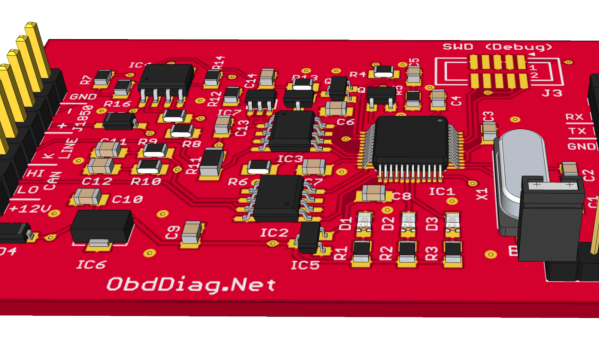
I’ve been working on a small board which will plug into my car and give direct access to speed reported on the Controller Area Network (CAN bus).

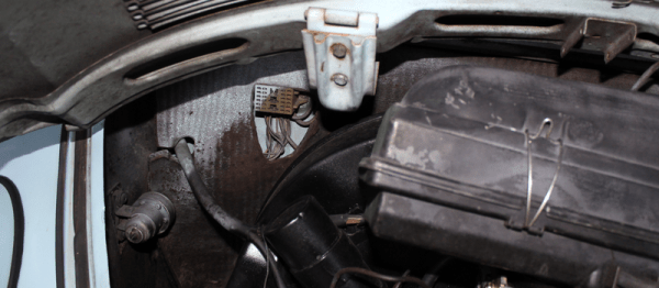
To back up a bit, my last video post was about my inane desire to make a small assembly that could plug into the OBDII port on my truck and create a series of pulses representing the speed of the vehicle for my GPS to function much more accurately. While there was a wire buried deep in the multiple bundles of wires connected to the vehicle’s Engine Control Module, I have decided for numerous reasons to create my own signal source.

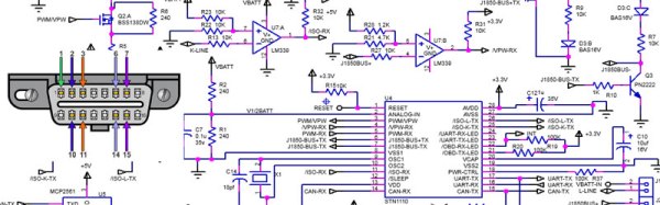
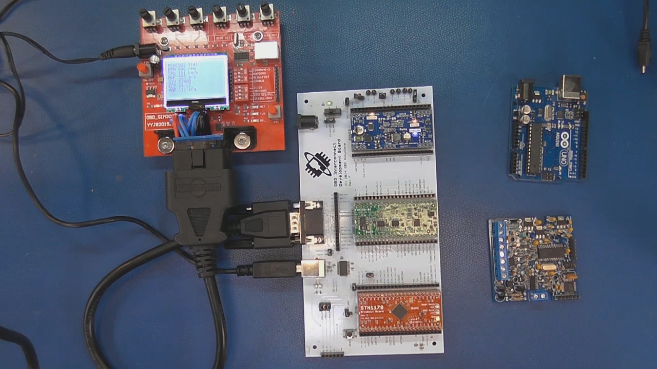
At the heart of my project is the need to convert the OBDII port and the underlying CAN protocol to a simple variable representing the speed, and to then covert that value to a pulse stream where the frequency varied based on speed. The OBDII/CAN Protocol is handled by the STN1110 chip and converted to ASCII, and I am using an ATmega328 like found on a multitude of Arduino’ish boards for the ASCII to pulse conversion. I’m using hardware interrupts to control the signal output for rock-solid, jitter-free timing.

Walk through the process of using an In-Circuit Emulator in the video below, and join me after the break for a few more details on the process.

Continue reading “Building An OBD Speed Pulse: Behold The ICE”

OBD-II Dongle Attack: Stopping A Moving Car Via Bluetooth

Researchers from the Argus Research Team found a way to hack into the Bosch Drivelog ODB-II dongle and inject any kind of malicious packets into the CAN bus. This allowed them to, among other things, stop the engine of a moving vehicle by connecting to the dongle via Bluetooth.

Drivelog is Bosch’s smart device for collecting and managing your vehicle’s operating data. It allows a user to connect via Bluetooth to track fuel consumption and to be alerted when service is necessary. It was compromised in a two stage attack. The first vulnerability, an information leak in the authentication process, between the dongle and the smart phone application allowed them to quickly brute-force the secret PIN offline and connect to the dongle via Bluetooth. After being connected, security holes in the message filter of the dongle allowed them to inject malicious messages into the CAN bus.

The Bluetooth pairing mechanism, called “Just Works”, has been fixed by Bosh by activating a two-step verification for additional users to be registered to a device.  The second issue, the ability for a maliciously modified mobile application to possibly send unwanted CAN messages, will be mitigated with an update to the dongle firmware to further limit the allowed commands that the dongle is able to place on the CAN bus.

Bosch downplays the issue a bit in their statement:

It is important to note that scalability of a potential malicious attack is limited by the fact that such an attack requires physical proximity to the dongle. This means that the attacking device needs to be within Bluetooth range of the vehicle.

The problem is that physical proximity does not equal Bluetooth range. Standard Bluetooth range is about 10m, which is very arguable physical proximity, but it is pretty easy to buy or even modify a Bluetooth dongle with 10x and 100x more range. When adding a wireless connection to the CAN bus of an automobile, the manufacturer has an obligation to ensure the data system is not compromised. This near-proximity example is still technically a remote hack, and it’s an example of the worst kind of vulnerability.

Bil Herd Asks OBD “How Fast Am I Going?”

Whenever I end up with a new vehicle I ultimately end up sticking in a new GPS/Receiver combination for better sound quality and a better GPS.

I am quite at home tearing into a dashboard as I was licensed to install CB radios in my teens as well as being the local go-to guy for 8-track stereo upgrades in the 70’s. I have spent a portion of my life laying upside down in a puddle on the car floor peering up into the mess of wires and brackets trying to keep things from dropping on my face. If you remember my post on my Datsun 280ZXT, I laid in that same position while welding in a clutch pedal bracket while getting very little welding slag on my face. I did make a note that the next time I convert a car from an automatic to a manual to do so while things are still disassembled.image15

Swapping out a factory radio usually involves choosing whether to hack into the existing factory wiring wire-by-wire, or my preference, getting a cable harness that mates with the factory plug and making an adapter out of it by splicing it to the connector that comes with the new radio.

Usually I still have to hunt down a few signals such as reverse indicator, parking brake indicator, vehicle speed sensor and the like. In my last vehicle the Vehicle Speed Sensor (VSS) wire was supposed to be in the factory harness, but driving experience showed it must not be as the GPS would show me driving 30 feet to the right of the highway. That and the calibration screen on the GPS verified that it was not receiving speed pulses.

Continue reading “Bil Herd Asks OBD “How Fast Am I Going?””

Maintenance, Emissions, And Privacy: The OBD Story

The 90s were a pivotal time in world history, and 1996 was no different. You might have spent the year glued to the TV playing Super Mario 64, or perhaps you were busy campaigning for Bill Clinton or Bob Dole, or maybe you were so depressed that Princess Diana and Prince Charles divorced that you spent the whole year locked in your room, a prisoner of your own existential nihilism. Whatever you did, though, it’s likely that one major event passed you by without a thought: The standardization of on-board vehicle diagnostics (in the US), otherwise known as OBD-II.

In the 1970s, vehicles (in some western countries, at least) were subject to ever-increasing restrictions on emissions. Most companies began switching from carburetors to efficient fuel injection systems, but even that wouldn’t be enough for the new standards. Cars began to carry rudimentary computer systems to manage and control the influx of valves, meters, and sensors that became the new norm. And, as one would guess, every car company had their own standard for managing and monitoring these computer systems. Eventually they would settle on the OBD system that we have today.

Continue reading “Maintenance, Emissions, And Privacy: The OBD Story”

Open Source OBD-II Adapter

Automotive diagnostics have come a long way since the “idiot lights” of the 1980s. The current version of the on-board diagnostics (OBD) protocol provides real time data as well as fault diagnostics, thanks to the numerous sensors connected to the data network in the modern vehicle. While the hardware interface is fairly standardized now, manufacturers use one of several different standards to encode the data. [Alex Sidorenko] has built an open source OBD-II Adapter which provides a serial interface using the ELM327 command set and supports all OBD-II standards.

The hardware is built around the LPC1517 Cortex-M3 microprocessor and can accept a couple of different versions. Here’s the PDF schematic, and a set of Gerber files (ZIP archive) for the PCB layout, if you’d like to dig in to it’s internals. The MC33660 ISO K Line Serial Link Interface device is used to provide bi-directional half-duplex communication interface with the micro-controller. Also included is the TJF1051, a high-speed CAN transceiver that provides an interface between the micro controller and the physical two-wire CAN lines on the ODB-II connector. The serial output from the adapter board is connected to a computer using a serial to USB adapter.

The software is written in C++ for the LPCXpresso IDE – a GNU tool chain for ARM Cortex-M processors, but can also be compiled using a couple of other toolchains. He’s got instructions if you’d like to build the firmware from source, or if you’d like to program the adapter via Flash Magic.

We featured [Alex]’s inexpensive PIC based ODB-II interface way back in 2007, so he’s been working on this for a while and has a good grip on what he’s doing.

OBD-II TrckrX: Data Logging In A BMW E36 M3

[Bruce Land] sent in this cool final project for ECE 4760 at Cornell University. Dubbed TrckrX, it is an OBD-II tracking and data logging system built into a BMW E36 M3. The car in question is being used in some auotocross competitions. The driver wanted instant access to some data as well as a log of everything for later analysis. The unit gives a real time display of vehicle speed, coolant temp, and RPM. G-force and timestamps are stored on the SD card.

We think this is a very cool idea, and could be quite useful in some instances. The real time display of speed and RPM seem a bit peculiar as the car’s speedometer and tachometer are more appropriately placed for real time information. However, we completely understand that this was a class project and this person may not have wanted to replace their dash cluster with a new readout.

Keep Tabs On Your Car Without OBD-II

[Steve] let us know about his MultiDisplay car monitoring system. Unlike traditional systems that rely on interfacing with the OBD-II protocol and existing car computer, the MultiDisplay uses an Arduino and custom shield with a combination of sensors; including temperatures, pressures, throttle, Boost, and etc. The data collected can then be displayed on a 20×4 LCD or streamed to a PC with visualization and event recording.

It’s nice to see half a years worth of work finally be complete and presented in such a clean and professional manner, keep up the good work [Steve]