Finding The Right Hack Is Half The Battle

Sometimes you just get lucky. I had a project on my list for a long time, and it was one that I had been putting off for a few months now because I loathed one part of what it entailed — sensitive, high-accuracy analog measurement. And then, out of the blue I stumbled on exactly the right trick, and my problems vanished in thin air. Thanks, Internet of Hackers!

The project in question is a low-vacuum regulator for “bagging” fiberglass layups. What I needed was some way to read a pressure sensor and turn on and off a vacuum pump accordingly. The industry-standard vacuum gauges are neat devices, essentially a tiny little strain gauge on a membrane between the vacuum side and the atmosphere side, in a package the size of a dime. (That it’s a strain gauge is foreshadowing, but I didn’t know that at the time.) I bought one for $15 ages ago, and it sat on my desk, awaiting its analog circuitry.

See, the MPX2100 runs on 12 V and puts out a signal around 40 mV on top of a 6 V offset. That voltage level is inconvenient for modern 3.3 V microcontroller ADCs, and the resolution would get clobbered by the 6 V signal if I just put a voltage divider on it. This meant whipping together some kind of instrument amplifier circuit to null out the 6 V and amplify the 40 mV for the ADC. The circuits I found online all called for 1% resistors in values I didn’t have, and mildly special op-amps. No fun, for me at least. So there it sat.

Picture of sketchy-looking vacuum apparatus.
Cut the blue wire or the red wire? HX711 module and pressure sensor on the left.

Until I ran into this project that machetes through the analog jungle with one part, and it happened to be one I had on hand. A vacuum pressure sensor is a strain gauge, set up like a Wheatstone bridge, just like you would use for weighing something with a load cell. The solution? A load-cell ADC chip, the HX711, found in every cheap scale or online for under a buck. The only other trick was finding a low-voltage pressure sensor to work with it, but that turns out to be easy as well, and I had one delivered in two days.

In all, this project took months of foot-dragging, but only a few clicks and five minutes of soldering once I got the right idea. The industrial applications and manufacturers’ app notes all make sense if you are making hundreds or millions of these devices, where the one-time cost of prototyping up the hard bits gets amortized, but the hacker solution of using a weight-scale chip was just the ticket for a one-off. That just goes to show how useful sharing our tips and tricks can be — you won’t get this from the industry. So send us your success stories, and your useful failures too, and Read More Hackaday!

SLA printer rigged for time lapse

Silky Smooth Resin Printer Timelapses Thanks To Machine Vision

The fascination of watching a 3D printer go through its paces does tend to wear off after you spent a few hours doing it, in which case those cool time-lapse videos come in handy. Trouble is they tend to look choppy and unpleasant unless the exposures are synchronized to the motion of the gantry. That’s easy enough to do on FDM printers, but resin printers are another thing altogether.

Or are they? [Alex] found a way to make gorgeous time-lapse videos of resin printers that have to be seen to be believed. The advantage of his method is that it’ll work with any camera and requires no hardware other than a little LED throwie attached to the build platform of the printer. The LED acts as a fiducial that OpenCV can easily find in each frame, one that indicates the Z-axis position of the stage when the photo was taken. A Python program then sorts the frames, so it looks like the resin print is being pulled out of the vat in one smooth pull.

To smooth things out further, [Alex] also used frame interpolation to fill in the gaps where the build platform appears to jump between frames using real-time intermediate flow estimation, or RIFE. The details of that technique alone were worth the price of admission, and the results are spectacular. Alex kindly provides his code if you want to give this a whack; it’s almost worth buying a resin printer just to try.

Is there a resin printer in your future? If so, you might want to look over [Donald Papp]’s guide to the pros and cons of SLA compared to FDM printers.

Continue reading “Silky Smooth Resin Printer Timelapses Thanks To Machine Vision”

an image of maketime showing the current time

Unique Clock Doubles As A Development Board

Most clocks these days have ditched the round face and instead prefer to tell time through the medium of 7-segment displays. [mihai.cuciuc] is bringing the round face to digital clocks with his time-keeping piece, MakeTime.

MakeTime's custom PCBMakeTime serves two purposes, the first and most obvious one is as a clock. Rather than displaying the time with digits, MakeTime harkens back to round dial clocks by illuminating RGB LEDs along its perimeter to show the position of the minute and hour “hands”. By using 24 LEDs, MakeTime achieves a timing granularity of 2.5 minutes.

The second purpose is as a development platform. [mihai.cuciuc] designed the clock with hacking in mind, opting to build it with components that many are already familiar with, such as a DS3231 RTC and WS2812 LEDs. To make the entire thing Arduino compatible, the microcontroller is an AtMega 328P, that can be connected to through the micro-USB port and CH340 USB-UART IC. If MakeTime outlives its time as a clock, all of the unused GPIO of the 328P are broken out to a single pin header, allowing it to be repurposed in other projects for years to come.

It seems like everyone is making their own unique timekeeping device these days. Check out the clock made out of ammeters we covered last week.

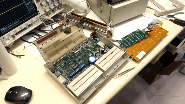
Automatic Microfiche Scanner Digitizes Docs

While the concept might seem quaint to us today, microfiche was once a very compelling way to store and distribute documents. By optically shrinking them down to just a few percent of their original size, hundreds of pages could be stored on a piece of high-resolution film. A box of said films could store the equivalent of several gigabytes of text and images, and reading them back only required a relatively simple projection machine.

As [Joerg Hoppe] explains in the write-up for his automatic microfiche scanner, companies such as Digital Equipment Corporation (DEC) made extensive use of this technology to distribute manuals, schematics, and even source code to their service departments in the 70s and 80s. Luckily, that means hard copies of all this valuable information still exist in excellent condition decades after DEC published it. The downside, of course, is that microfiche viewers aren’t exactly something you can pick up at the local Big Box electronics store these days. To make this information accessible to current and future generations, it needs to be digitized.

The camera panning over a full DEC microfiche sheet.

[Joerg] notes there are commercial services that would do this for you, but the prices are just too high to be practical for the hobbyist. The same for turn-key microfiche scanners. Which is why he’s developed this hardware and software system specifically to digitize DEC documents. The user enters in the information written on the top of the microfiche into the software, and then places it onto the machine itself which is based on a cheap 3D printer.

The device moves a Canon DSLR camera and appropriate magnifying optics in two dimensions over the film, using the Z axis to fine-tune the focus, and then commands the camera to take an image of each page. These are then passed through various filters to clean up the image, and compiled into PDFs that can be easily viewed on modern hardware. The digital documents can be further run though optical character recognition (OCR) so the text can be easily searched and manipulated. In the video after the break you can see that the whole process is rather involved, but once the settled into the workflow, [Joerg] says his scanner can digitize 100 pages in around 10 minutes.

A machine like this is invaluable if you’ve got a trove of microfiche documents to get through, but if you’ve just got a sheet or two you’d like to take a peek at, [CuriousMarc] put together a simple rig using a digital microscope and a salvaged light box that should work in a pinch.

Continue reading “Automatic Microfiche Scanner Digitizes Docs”

A MetaSense joystick

3D-Printing Complex Sensors And Controls With Metamaterials

If you’ve got a mechatronic project in mind, a 3D printer can be a big help. Gears, levers, adapters, enclosures — if you can dream it up, a 3D printer can probably churn out a useful part for you. But what about more complicated parts, like sensors and user-input devices? Surely you’ll always be stuck buying stuff like that from a commercial supplier. Right?

Maybe not, if a new 3D-printed metamaterial method out of MIT gets any traction. The project is called “MetaSense” and seeks to make 3D-printed compliant structures that have built-in elements to sense their deformation. According to [Cedric Honnet], MetaSense structures are based on a grid of shear cells, printed from flexible filament. Some of the shear cells are simply structural, but some have opposing walls printed from a conductive filament material. These form a capacitor whose value changes as the distance between the plates and their orientation to each other change when the structure is deformed.

The video below shows some simple examples of monolithic MetaSense structures, like switches, accelerometers, and even a complete joystick, all printed with a multimaterial printer. Designing these structures is made easier by software that the MetaSense team developed which models the deformation of a structure and automatically selects the best location for conductive cells to be added. The full documentation for the project has some interesting future directions, including monolithic printed actuators.

Continue reading “3D-Printing Complex Sensors And Controls With Metamaterials”

Banish Early Morning Zombification With The Zom-b-gone!

[Applied Procrastination] aka [Simen E. Sørensen] has a simple project to help those of us that struggle with early-morning zombification. By leveraging the backlight optics from a broken LCD monitor, it is possible to create an excellent diffused light source to simulate daylight, before your chosen waking time. The theory is that it is less shocking to the brain to be woken more gradually than an alarm may do. The increasing light level is to prepare the brain with a slowly increasing light level, reminiscent of daybreak, before being properly awoken by an alarm, regardless of the actual light level outdoors. This particularly useful for those of us in more northern regions, such as [Simen]’s native Norway, where mornings are very dark in the winter months.

Daylight is not purely a diffuse source however, it depends on the degree of atmospheric scattering, local reflections and such, but as far as we’re concerned here, we can just aim for as diffuse a light source a possible.

Source: DOI:10.1117/12.797854

The implementation makes use of the existing LCD metal frame, the light guide panel (usually a big hunk of acrylic covered in etched markings on one side) the diffuser/brightener sheet, and the prism sheet. A white LED strip mounted around the frame edge directs light into the light guide, which with a combination of total internal reflection and scattering on one side only, effectively turns the light through 90 degrees, and spreads it out evenly across that surface. The result of this optical sandwich is flat, even light, exactly what you want for a display, and also for simulating daylight.

Nestled beneath the expected 3D printed frame, is a custom PCB derived by smooshing together the designs from the Adafruit DS3231 RTC module and the Arduino Nano, an additional push button and rotary encoder complete the minimalistic UI, and allow the device to double up as general purpose lamp during the day. Despite a few wobbles with assembling the frame, and some incorrect PCB footprinting, the whole thing came together pretty nicely. This is a perfect thing to do with broken LCD monitors, eeking out a new life and keeping the amount of landfill to a minimum.

For further details of the hardware and codes, see the Zom-b-Gone Github.

Continue reading “Banish Early Morning Zombification With The Zom-b-gone!”

Putting An Afterburner On An Electric Ducted Fan

Afterburners are commonly agreed to be the coolest feature of military fighter aircraft. Injecting raw fuel into the exhaust stream of a jet engine, afterburners are responsible for that red-hot flaming exhaust and the key to many aircraft achieving supersonic flight. [Integza] wanted to see if the same concept could be applied to an electric ducted fan, and set out to find out.

Of course, building an afterburner for an EDF does add a lot of complication. A flame tube was installed downstream of the EDF, fitted with a brass tube drilled carefully to act as a fuel injector. The flame tube was also fitted with an automotive glow plug in order to ignite the fuel, which was lighter refill gas straight from a can. The whole assembly is wrapped up inside a clear acrylic tube that allows one to easily see what’s happening inside with the combustion.

Results were mixed. While the fuel did combust, but in a rather intermittent fashion. In proper operation, an afterburner would run with smooth, continuous, roaring combustion. Additionally, no thrust measurements were taken and the assembly barely shook the desk.

Thus, if anything, the video serves more as a guide of how to burn a lot of lighter gas with the help of an electric fan. The concept does has merit, and we’ve seen past attempts, too, but we’d love to see a proper set up with thrust readings with and without the afterburner to see that it’s actually creating some useful thrust. Video after the break.  Continue reading “Putting An Afterburner On An Electric Ducted Fan”