Silicon Jumpers Make This Wire-Free Breadboard Programmable

There’s no doubting the utility of the trusty solderless breadboard, but you have to admit they’re less than perfect. They’re not ideal for certain types of circuits, of course, but that’s less of a problem than those jumper wires. The careless will end up with their components hopeless tangled in a rat’s nest of jumpers, while the fastidious will spend far more time making the jumpers neat and tidy than actually prototyping the circuit itself. What to do?

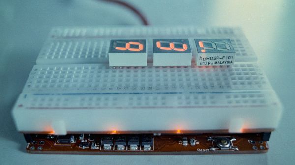
One way to crack this nut is to make the solderless breadboard jumperless, too. That’s the idea behind “breadWare” a work-in-progress undertaken by [Kevin Santo Cappuccio]. The idea is to adapt a standard breadboard so that connections between arbitrary pairs of common contact strips — plus the power rails — can be made in software. The trick behind this is a matrix of analog CMOS switch chips, specifically the MT8816AP. Each chip’s 128 crosspoint switches can handle up ± 12 volts, so there are plenty of circuits that can use these programmable silicon jumpers.

[Kevin] is currently on version 0.2, which is sized to fit under a solderless breadboard and make a compact package. He shared details on how he’s connecting to the breadboard contacts, and it looks like a painful process: pull out the contact, cut a small tab at the gutter-end, and bend it down so it forms a lead for a through-hole in the PCB. It seems like a lot of work, and there must be a better way; [Kevin] is clearly open to suggestions.

While we’ve seen crosspoint switching used to augment solderless breadboarding before, we find this project pleasing in its simplicity. The thought of tossing out all those jumpers is certainly tempting.

PipeWire, The Newest Audio Kid On The Linux Block

Raise your hand if you remember when PulseAudio was famous for breaking audio on Linux for everyone. For quite a few years, the standard answer for any audio problem on Linux was to uninstall PulseAudio, and just use ALSA. It’s probably the case that a number of distros switched to Pulse before it was quite ready. My experience was that after a couple years of fixing bugs, the experience got to be quite stable and useful. PulseAudio brought some really nice features to Linux, like moving sound streams between devices and dynamically resampling streams as needed.

Continue reading “PipeWire, The Newest Audio Kid On The Linux Block”

Big Spinning Disk Makes A Small Color Video Display

Believe it or not, the Mickey Mouse clip used for this demonstration is actually in the public domain.

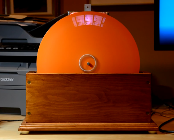
The earliest televisions used a spinning disk technology called the Nipkow disk, which is exactly what [Science ‘n’ Stuff] recreated with their Arduino-based mechanical color television (video link, also embedded below.) The device reads video and audio from an SD card, and displays the video using a precisely-timed RGB LED visible through a perforated spinning disk. The persistence of vision effect results in a video that is small, relative to the size of the disk, but perfectly watchable. A twist is that the video is in color!

A Nipkow disk is a fairly simple and electromechanical device that relies on timing; something a modern microcontroller and RGB LED is perfectly capable of delivering. In this device, the holes in the disk create 32 vertical scanlines with 96 “pixels” making up each of those lines. Spinning disk technology was always limited to being monochromatic, but in this implementation, each “pixel” is given its own unique color by adjusting the RGB LED accordingly.

The first video shows off the device and demonstrates it working; note that it may look like there are multiple little screens, but the center one can be thought of as the “true” display with the others essentially being artifacts due to light leakage. If you’re interested in the nuts and bolts of exactly how a Nipkow disk works, then the second video is what you’ll be more interested in, because it goes through all the details of exactly how everything functions.

Another neat thing about Nipkow disks is that image acquisition is really not much more complex than image display.

[via Arduino Blog]

Continue reading “Big Spinning Disk Makes A Small Color Video Display”

Graphene lattice

How Graphene May Enable The Next Generations Of High-Density Hard Drives

After decades of improvements to hard disk drive (HDD) technology, manufacturers are now close to taking the next big leap that will boost storage density to new levels. Using laser-assisted writes, manufacturers like Seagate are projecting 50+ TB HDDs by 2026 and 120+ TB HDDs after 2030. One part of the secret recipe is heat-assisted magnetic recording (HAMR).

One of the hurdles with implementing HAMR is finding a protective coating for the magnetic media that can handle this frequent heating while also being thinner than current coatings, so that the head can move even closer to the surface. According to a recent paper by N. Dwivedi et al. published in Nature Communications, this new protective coating may have been found in the form of sheets of graphene.

Continue reading “How Graphene May Enable The Next Generations Of High-Density Hard Drives”

Test Your ‘Blue Pill’ Board For A Genuine STM32F103C8 MCU

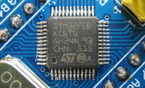
With the market for STM32F103C8-based ‘Blue Pill’ boards slowly being overrun with boards that contain either a cloned, fake or outright broken chip, [Terry Porter] really wanted to have an easy, automated way to quickly detect whether a new board contains genuine STM32 silicon, or some fake that tries to look the part. After more than a year of work, the Blue Pill Diagnostics project is now ready for prime time.

We have covered those clone MCUs previously. It’s clear that some of those ‘Blue Pill’ boards obviously do not have a genuine STM32 MCU on them, as they do not have the STM32 markings on them, while others fake those markings on the package and identifying can be hard to impossible. Often only testing the MCU’s actual functionality can give clarity on whether it’s a real STM32 MCU.

These diagnostics allow one to test not only the 64 kB of Flash, but also the 64 kB of ‘hidden’ Flash that’s often found on these MCUs (rebadged 128 kB STM32F103 cores). It further checks the manufacturer JDEC code and uses a silicon bug in genuine STM32F1xx MCUs where the BGMCU_IDCODE cannot be read without either SWD or JTAG connected.

Another interesting feature of Blue Pill Diagnostics is using Mecrisp-Stellaris Forth as its foundation, which allows for easy access to a Forth shell via this firmware as well, not unlike MicroPython and Lua, only in a fraction of the Flash required by those. We have previously written about using Mecrisp-Stellaris in your projects.

The Compromises Of Raspberry Pi Hardware Documentation

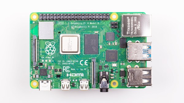
[Rowan Patterson] informed us about a recent ticket he opened over at the Raspberry Pi Documentation GitHub repository. He asked about the the lack of updates to the Raspberry Pi 4’s USB-C power schematics for this board. You may recall that the USB-C power issue was covered by us back in July of 2019, yet the current official  Raspberry Pi 4 schematics still show the flawed implementation, with the shorted CC pins, nearly two years later.

[Alasdair Allan], responsible for the Raspberry Pi  documentation, mentioned that they’re in the process of moving their documentation from Markdown to AsciiDoc, and said that they wouldn’t have time for new changes until that was done. But then [James Hughes], Principal Software Engineer at Raspberry Pi,  mentioned that the schematics may not be updated even after this change due to a of lack of manpower.

As [James] emphasized, their hardware will probably never be open, due to NDAs signed with Broadcom. The compromise solution has always been to publish limited peripheral schematics. Yet now even those limited schematics may not keep up with board revisions.

An easy fix for the Raspberry Pi 4’s schematics would be for someone in the community to reverse-engineer the exact changes made to the Raspberry Pi 4 board layout and mark these up in a revised schematic. This should be little more than the addition of a second 5.1 kΩ resistor, so that CC1 and CC2 each are connected to ground via their own resistor, instead of being shorted together.

Still, you might wish that Raspberry Pi would update the schematics for you, especially since they have updated versions internally. But the NDAs force them to duplicate their efforts, and at least right now that means that their public schematics do not reflect the reality of their hardware.

Modifying A SNES Rom To Be Widescreen

Turning a game like Super Mario World for SNES into a widescreen game is not a small task, but [Vitor Vilela] accomplished just that. [Vitor] has a long list of incredible patches such as optimizing code for better frame rates and adding code to take advantage of the SA-1 accelerator chip, so out of anyone he has the know-how to pull a widescreen mod off. This patch represents a true labor of love as many levels were designed with a specific screen width in mind. [Vitor] went through each of these single-screen width levels and expanded them by writing the extra assembly needed.

On a technical level, this hack was achieved by using the panning feature built into the game. The left and right shoulder buttons allowed a player to pan the camera to the left and right. The viewport is considered to be two times the screen resolution and so items will be rendered within the widescreen resolution. By taking away the panning feature and render a larger section of the viewport to the screen, you get a widescreen view. However, to save cycles, enemies and items don’t start moving until they get close to the screen edge. So how do you make a game widescreen without ruining the timing of every enemy that spawns? Suddenly the hours of muscle memory that fans have drilled in over the years is a disadvantage rather than a strength. The answer is a significant time investment and an eye for detail.

All the code is available on GitHub. A video of a playthrough of the mod is after the break.

Continue reading “Modifying A SNES Rom To Be Widescreen”