A Transistor-less Sound Synthesizer

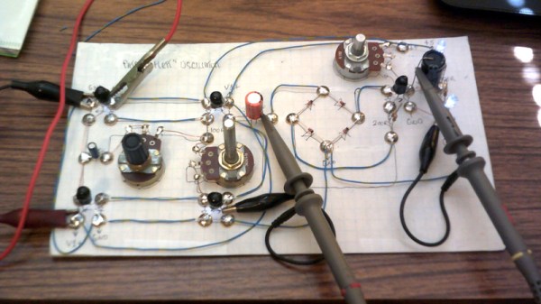
A synthesizer without transistors could almost be the basis of a trick question, surely without transistors it must be using a vacuum tube or similar. Not [Dr. Cockroach]’s synth though, instead of transistors it uses coupled pairs of LEDs and light-dependent resistors as its active components. Its oscillator circuit comes courtesy of [Patrick Flett], and uses a pair of LED/LDR combinations to alternately charge and discharge a capacitor. This feeds another LDR/LED pair that appears to act as a buffer to drive a bridge rectifier, with a final amplifier following it.

The result oscillates, though at frequencies in the low audio range with a cluster of harmonics thrown in. Its sound is best described as something akin to a small single-cylinder motorcycle engine at the lower frequencies, and is something we see could have all sorts of interesting possibilities.

This approach of using LDR-based active devices may be something of a dead end that could have had its day back in the 1930s, but it’s nevertheless an entertaining field to explore. It’s not the first time we’ve followed [Dr. Cockroach] at it, in the past we’ve seen the same technique applied to logic gates.

Have a listen to the synth in the video below the break. Continue reading “A Transistor-less Sound Synthesizer”

Let The Solar Free

Anyone tackling solar power for the first time will quickly find there’s a truly dizzying amount of information to understand and digest. You might think you just need to buy some solar panels, wire them together, and just sort of plug them in. But there are a hundred and one different questions about how they’ll be connected, the voltage of the panels, and the hardware for driving a load. [Michel], [case06], and [Martin Jäger] have set out to create a simpler and easier to understand charge controller named LibreSolar.

a diagram showing how the libre solar is wired up

A charge controller is fundamentally a simple idea. The goal is to charge a battery with solar panels, which means it’s essentially just a heavy-duty DC/DC buck converter. What makes this project different is that it is an open platform built for extensibility.

There are UEXT connectors included for adding extra peripherals, and with some tweaks to the STM32 firmware, it would be easy to handle small wind turbines (with some rectification to convert to DC, of course). LibreSolar seems to be designed with an eye towards creating a nano-scale localized networked grid. For example, they’ve developed a Raspberry Pi Zero module that uses WiFi to create a CAN bus allowing the boxes to communicate their maximum voltage to each other. This makes the system as plug-and-play as possible, as the bus doesn’t require a master controller to communicate.

With features such as MPPT (Maximum Power Point Tracking), 20 amp peak charging, a USB interface for updating, and several built-in protection mechanisms, it’s clearly a well thought through project. We look forward to seeing it deployed in the real world!

Optical Centrepunch Is An Easy Build If You Need One

Tired of getting his centerpunches thereabouts but not quite there, [Uri] decided something had to be done. A common tool to solve this problem is the optical centerpunch, but models on sale were just a little too pricy for something so basic. Instead, [Uri] elected to build his own.

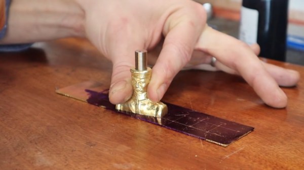
An optical centerpunch is a simple tool that helps machinists hit a centerpunch dead on target, time after time. A guide is used that holds a clear plastic rod with a dot in the center. This dot is lined up over the spot to be centerpunched. The plastic rod is then removed and replaced with the actual punch that does the work. Not content to build something utilitarian, [Uri] instead sculpted the tool into a likeness of Sgt Pepper (of Yellow Submarine fame). Seeing the hunk of bare brass quickly become a recognisable figure on camera is a testament to [Uri’s] skill as a sculptor.

It’s a tool that can be readily built by anyone with a lathe, or, at the very least, a decent drill press. We imagine it would be particularly useful for those without perfect vision, making it easier to get punches on the mark on a regular basis. [Uri] has graced these pages before, too — he previously built an ornate tool to make all the other hammers jealous. Video after the break.

Continue reading “Optical Centrepunch Is An Easy Build If You Need One”

Get Over Your Fears

Some projects are just too complex, that’s for sure. But I’d be willing to bet that some things you think are too difficult actually aren’t, and it may be that all you need to get over your personal hurdle is a good demonstration. Here come three cases in point.

I was looking at the new Raspberry Pi Compute Module last weekend. They have a whole bunch of high-speed traces: things like Gigabit Ethernet, HDMI, and those crazy-fast SDI serial camera interfaces. I have no experience in high-speed design and layout at all, and frankly it gives me the willies. But the Raspberries also shipped me an IO demo board, and concomitant KiCAD design files, with the review board. Looking at it, they were just wires — maybe pairwise length-matched and impedance controlled — but also just wires. Opening up the KiCAD board file and clicking on the traces just like I do with my own designs, I’m a lot less scared. That was a revelation for me.

In a great writeup of his experience building ten different Linux single-board-computers from scratch, Jay Carlson had a similar effect on me. I would never have considered breaking out the hotplate for some CPU-and-DRAM action, and I’ve never had to lay out a PCB with a high density BGA chip before either. I’m not quite into Dunning-Kruger territory yet; I still have a healthy respect for the layout intricacies in fanning out a tight BGA CPU into a DRAM. But Jay’s frank assessments of what is easy and what is hard make it all seem within the realm of the doable.

As Mike and I were talking on the podcast about Jay’s work, Mike came clean about his fear of BGAs. I’ve done enough reflow-plate soldering, with parts that have a lead pitch that’s a factor of two finer than the 0.8 mm pitch BGAs in question, so it doesn’t seem implausible to me. And I’m 100% sure Mike could pull it off too, but he is in need of a BGA guru. Any good hobbyist videos out there?

Being a nerdy type, I’m much more focused on the knowledge and the inspiration, but maybe the courage is equally important — at least I think I undervalue it. I don’t need to lay out HDMI lines, or build a from-scratch Linux box, but I am no longer afraid that I couldn’t, and that’s because I’ve seen detailed examples of fellow hackers who’ve done the same. I might not get it right on the first shot, but I’m not afraid to try, and I wouldn’t have said the same before looking over other folks’ shoulders. Forza e corragio!

Super-Simple VGA Adapter Sports Low-Res Output With Only Four TTL Chips

Here at Hackaday we cast a wary eye at tips that come in with superlative claims. Generally, if we post something that claims to be the fastest or the smallest of all time, we immediately get slapped down in the comments by someone who has done it faster or smaller. So we present the simplest TTL video card ever knowing the same thing will happen, but eager to see how anyone might scale things down.

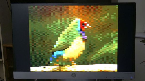
To be fair, [George Foot] does qualify his claim to the simplest usable VGA adapter, and he does note that it descends from [Ben Eater]’s “world’s worst video card”, which he uses for his 6502 breadboard computer. But where [Ben]’s VGA adapter uses about 20 TTL chips and an EEPROM, [George] has managed to decrease the BOM to just four TTL chips along with the memory and a crystal oscillator. This required a fair number of compromises, of course; the color depth is fairly low, as is the resolution. Each pixel appears as a thin horizontal bar rather than a small square, leading the images to be smeared out across the screen. They’re still surprisingly viewable, though, which probably says more about the quality of the pattern-recognition wetware between our ears than anything about the quality of the adapter. [George] gives a tour of the circuit in the brief video below.

It looks like [George] has posted a few improvements to the project since we first spotted it, so we’re looking forward to seeing how much the parts count went up. We’re also keen to see if anyone can outdo the simplicity of this effort — be sure to let us know if you give it a shot.

Continue reading “Super-Simple VGA Adapter Sports Low-Res Output With Only Four TTL Chips”

Proprietary Lenses Are No Problem With This USB Adaptor

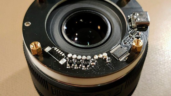
There was a time when a camera lens was simply a set of shaped pieces of glass in a tube, with a mount and an aperture. But as cameras have embraced electronics ever more, technology has found its way past the lens mount to the extent that all features of a modern lens are electronically controllable. Can they be used outside the confines of the camera they were designed for? If the user is [Jana Marie] then certainly, because she’s created a nifty USB adapter and mount for Canon lenses for use with her custom streaming camera.

The hardware is a 3D printed lens mount with a PCB that mates with the pins on the lens. An STM32 does the hard work and talks to the outside world through a USB interface, however it’s in the software that the real effort lies. The Canon lens protocol has been extended since the 1980s, and the commands for different generations of lenses can be convoluted. All the information is in a GitHub repository, so the curious hacker can roll their own.

There are a wealth of camera projects to be found for those that don’t mind tearing apart some of their more valuable possessions, and this isn’t the first we’ve seen involving the hacking of the Canon protocol.

Relay Computer Consumes Six Years And 4.5 Suitcases

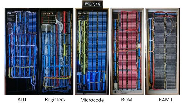
If you thought your home-brew project was taking a long time, [Jeroen Brinkman]’s MERCIA Relay Computer project probably has you beat. He began working on this impressive computer back in 2014, and has been at it ever since.  In fact, the ongoing nature of the project is embedded into the name itself — the English translation of the acronym MERCIA is “My Simple Relay Computer Under Construction”.  Being interested in old analog and relay computers from an early age, [Jeroen] took on this project to educate students about how computers work.  The entire computer is build only using relays, diodes, and capacitors, not to mention color-coded wire based on signal functions. Using relays as the primary switching elements is at the core of his educational goal — anyone can understand how a relay works.

Understandably, this thing is big.  But he has cleverly packaged it to visually show the major building blocks of a computer.  While the exact size isn’t stated, we can estimate based on the photo of [Jeroen] standing next to the modules that these panels are about 1.5 m tall and perhaps 60 cm wide.  The whole computer is nine panels wide, making it about 5 meters long.  Except for the ROM assembly, pairs of panels are hinged together and they fold like a book and carried like a suitcases when being moved.  If you enjoy the clickety-clack sound of relays, be sure to watch the relay longevity test in the video below and check out our article on the 1958 FACOM from last year.

This is a fascinating project, but unless you have a couple thousand relays laying around and a decade of free time, it’s probably better to just enjoy [Jeroen]’s work rather than build your own.  We hope he releases schematics and other documentation once the project is finished.  You can follow his Facebook build log if you want to keep track of the progress. Thanks to [David Gustafik] for the tip.

Continue reading “Relay Computer Consumes Six Years And 4.5 Suitcases”