The vast majority of us are satisfied with a standard, base ten display for representing time. Fewer of us like to be a bit old-fashioned and use a dial with a couple of hands that indicate the time, modulo twelve. And an even smaller minority, with a true love for the esoteric, are a fan of binary readouts. Well, there’s a new time-telling game in town, and as far as we’re concerned it’s one of the best ones yet: resistor color codes.
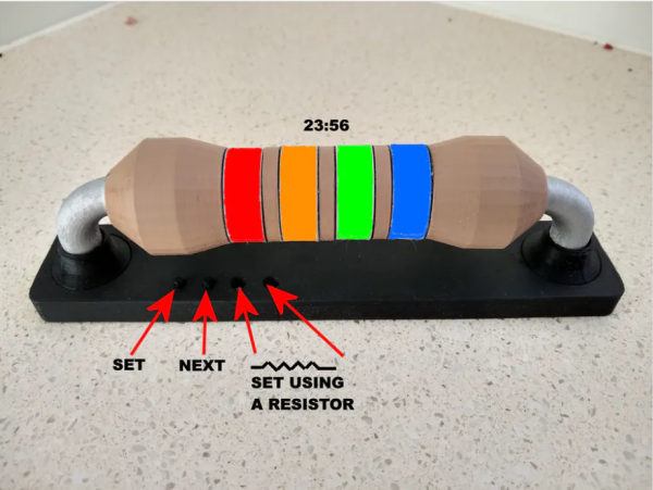
The Ohm Clock is, as you may have guessed, a giant model of a resistor that uses its color bands to represent time.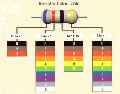 Each of the four bands represents a digit in the standard HH:MM representation of time, and for anybody well-versed in resistor codes this is sure to be a breeze to read. The clock itself was designed by [John Bradnam]. It’s body is 3D printed, with RGB LEDs to brightly illuminate each segment. The whole thing is controlled by an old favorite – an ATtiny, supported by a Real Time Clock (RTC) chip for accurate timekeeping.
You can set the time in the traditional fashion using buttons, or — and here’s the brilliant part — you can use a resistor. Yup, that’s right. Connecting a 220 Ohm resistor across two terminals on the clock will set the time to 2:20. Genius.
When you come across an art as old as timekeeping, it’s easy to assume that everything’s already been done. We have sundials, hourglasses, analog clocks, digital watches, those cool clocks that use words instead of numbers, the list goes on. That’s why it’s so exciting to see a new (and fun!) idea like this one emerge.