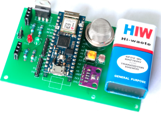
Remember those actions movies like The Fast and the Furious where cars are constantly getting smashed by fast flying bullets? What would it have taken to protect the vehicles from AK-47s? In [PrepTech]’s three-part DIY composite vehicle armor tutorial, he shows how he was able to make his own bulletproof armor from scratch. Even if you think the whole complete-collapse-of-civilization thing is a little far-fetched, you’ve got to admit that’s pretty cool.
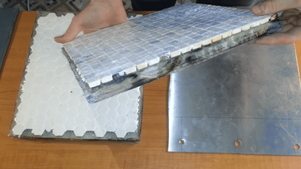
The first part deals with actually building the composite. He uses layers of stainless steel, ceramic mosaic tiles, and fiberglass, as well as epoxy resin in order to build the composite. The resin was chosen for its high three-dimensional cross-linked density, while the fiberglass happened to be the most affordable composite fabric. Given the nature of the tiny shards produced from cutting fiberglass, extreme care must be taken so that the shards don’t end up in your clothes or face afterwards. Wearing a respirator and gloves, as well as a protective outer layer, can help.
After laminating the fabric, it hardens to the point where individual strands become stiff. The next layer – the hard ceramic – works to deform and slow down projectiles, causing it to lose around 40% of its kinetic energy upon impact. He pipes silicone between the tiles to increase the flexibility. Rather than using one large tile, which can only stand one impact, [PrepTech] uses a mosaic of tiles, allowing multiple tiles to be hit without affecting the integrity of surrounding tiles. While industrial armor uses boron or silicon carbide, ceramic is significantly lower cost.
The stainless steel is sourced from a scrap junkyard and cut to fit the dimensions of the other tiles before being epoxied to the rest of the composite. The final result is allowed to sit for a week to allow the epoxy to fully harden before being subject to ballistics tests. The plate was penetrated by a survived shots from a Glock, Škorpion vz. 61, and AK-47, but was penetrated by the Dragunov sniper rifle. Increasing the depth of the stainless steel to at least a centimeter of ballistic grade steel may have helped protect the plate from higher calibers, but [PrepTech] explained that he wasn’t able to obtain the material in his country.
Nevertheless, the lower calibers were still unable to puncture even the steel, so unless you plan on testing out the plate on high caliber weapons, it’s certainly a success for low-cost defense tools.
Continue reading “Bullet-proofing Your Car With An Affordable Composite Armor”