Fourier Explained: [3Blue1Brown] Style!

If you ask most people to explain the Fourier series they will tell you how you can decompose any particular wave into a sum of sine waves. We’ve used that explanation before ourselves, and it is not incorrect. In fact, it is how Fourier first worked out his famous series. However, it is only part of the story and master video maker [3Blue1Brown] explains the story in his usual entertaining and informative way. You can see the video below.

Paradoxically, [3Blue1Brown] asserts that it is easier to understand the series by thinking of functions with complex number outputs producing rotating vectors in a two-dimensional space. If you watch the video, you’ll see it is an easier way to work it out and it also lets you draw very cool pictures.

Continue reading “Fourier Explained: [3Blue1Brown] Style!”

A Lot Of Volts For Not A Lot

There was a time when high voltage in electronic devices was commonplace, and projects driving some form of vacuum or ionisation tube simply had to make use of a mains transformer from a handy tube radio or similar. In 2019 we don’t often have the need for more than a few volts, so when a Geiger–Müller tube needs a bit of juice, we’re stumped. [David Christensen] approached this problem by creating his own inverter, which can produce up to 1 kV from a 12 V supply.

Instead of opting for a flyback supply he’s taken a traditional step-up approach, winding his own transformer on a ferrite core. It has a centre-tapped primary which he drives in push-pull with a couple of MOSFETS, and on its secondary is a voltage multiplier chain. The MOSFETs take their drive at between 25 kHz and 50 kHz from a 555 timer circuit, and there is no feedback circuit.

It’s fair to say that this is a somewhat hair-raising circuit, particularly as he claims that it is capable of delivering that 1 kV at 20 W. It’s usual for high-voltage supplies driving very high impedance loads to incorporate a set of high-value resistors on their outputs to increase their internal impedance such that their danger is reduced. We’d thus exercise extreme care around this device, though we can see a lot of value in his description of the transformer winding.

We can’t criticise this circuit too much though, because some of us have been known to produce far hackier high voltage PSUs.

A PDP Laptop, For Various Definitions Of A Laptop

Digital Equipment Corp.’s PDP-11 is one of the most important computers in history. It’s the home of Unix, although that’s arguable, and it’s still being used in every application, from handling nuclear control rods to selling Ed Sheeran tickets on Ticketmaster. As the timeline of PDP-11 machines progressed, the hardware did as well, and by the time the PDP was eclipsed by the VAXxen, there were PDP-11s on a single chip. The Eastern Bloc took notice and produced their own PDP-11 on a chip. This is the 1801-series CPU, and like most soviet electronics from the Cold War, they’re readily available on eBay.

[SHAOS] has an interesting project in mind for this PDP-on-a-chip. It’s a standalone computer built around the Soviet re-implementation of the PDP-11, built into a form factor that could be described as a single board computer.

This project is the outgrowth of [SHAOS]’ project for last year’s Hackaday Prize, the PDPii. This was a computer built around a backplane that replicated the PDP-11 using a KR1801VM2 CPU, the Soviet not-a-clone clone of the PDP-11. This project is basically a PDP-11/03 system, except it was made in this century, and you can put it in any computer case, with bonus points awarded for RGB lighting and liquid cooling.

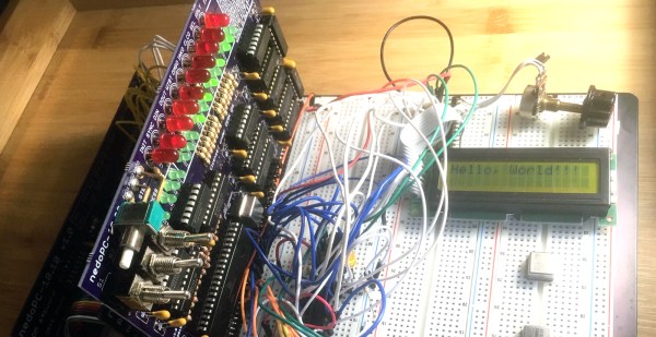
This year’s project, the PDPjr, eschews standardization to something that is far more unique. This build is more or less a single board computer with a character LCD display and a real keyboard. Think of this as the PDP-11 equivalent of the TRS-80 Model 100, a machine widely regarded as being the first laptop.

There’s still a lot of work to go, but [SHAOS] has written a ‘Hello World’ for this chip, and is getting those words to display on the character LCD. That’s a great first step and we can’t wait to see where this project ends up.

Project Egress: Two Ways To Latch The Hatch

With July slipping away and the deadline approaching, the Project Egress builds are pouring in now. And we’re starting to see more diversity in the choice of materials and methods for the parts being made, like these two latches made with very different methods by two different makers.

For the uninitiated, Project Egress is a celebration of both the 50th anniversary of Apollo 11 and the rise of the maker movement. Spearheaded by [Adam Savage], the idea is to engage 44 prominent makers to build individual parts from the Unified Crew Hatch (UCH) from the Apollo Command Module. The parts will be used to create a replica of this incredibly complex artifact, which will be assembled by [Adam] before a live audience at the National Air and Space Museum next week.

Both [Joel] from the “3D Printing Nerd” channel and [Bill Doran] from “Punished Props Academy” got the nod for one of the 15 latches needed, and both played to their respective strengths. [Joel]’s latch was executed in PLA on a Prusa I3 printer. [Bill] went a different route for his latch. He used a Form 2 SLA printer to print the parts, but used them only to make silicone molds. He then cast the parts from urethane resin, which should prove much stronger than the original SLA prints. We suspect the ability to quickly cast more latches could prove handy if any of the other latch makers should fail to deliver.

The latches [Joel] and [Bill] made joins the other parts, like the wooden latch being made by [Fran Blanche] and the hatch handle [Paul] cast in aluminum. We’re looking forward to more part builds, as well as the final assembly.

Continue reading “Project Egress: Two Ways To Latch The Hatch”

Minivac 601 Replica Gets A Custom Motorized Rotary Switch

One of the joys of electronics as a hobby is how easy it is to get parts. Literally millions of parts are available from thousands of suppliers and hundreds of distributors, and everyone competes with each other to make it as easy as possible to put together an order from a BoM. If you need it, somebody probably has it.

But what do you do when you need a part that doesn’t exist anymore, and even when it did was only produced in small numbers? Easy – you create it yourself. That’s just what [Mike Gardi] did with this unique motorized rotary switch he needed to complete his replica of a 1960s computer trainer. We covered his build of the Minivac 601, a trainer from the early computer age that let experimenters learn the ropes of basic digital logic. It used mostly relays, lamps, and switches connected by jumpers, but it had one critical component – a rotary control that was used for input and, with the help of a motor, as an output indicator.

[Mike]’s version of the switch is as faithful to the original as possible, at least in terms of looks. The parts are mostly 3D-printed, with 16 reed switches embedded in the walls and magnets placed in the rotor. The motor to operate the rotor is a simple gear motor mounted to a hinged bracket; when the rotor needs to move, a solenoid pulls the motor’s friction drive wheel up against the rotor.

The unique control slots right into the Minivac replica and really completes the look and feel. Hats off to [Mike] for a delightful replica of a lost bit of computer history and the dedication to see it through to completion.

Continue reading “Minivac 601 Replica Gets A Custom Motorized Rotary Switch”

A Wedding Gift Fit For A Hardware Hacker

If you read Hackaday on a regular basis, there are some names you will have seen more than once. People who continually produce fascinating and inventive projects that amaze and delight us, and who always keep us coming back for more. One such hacker is [Jeroen Domburg], perhaps better known in these pages by the handle [Sprite_TM], who has never failed to delight us in this respect.

Today is a special day for [Jeroen] for it is his wedding day, and his friend [Maarten Tromp] has decided to surprise him and his wife [Mingming] with a special gift. At first sight it is simply a pair of blinky badges in the shape of a bride and groom, but closer examination reveals much more. The PCBs are studded with WS2812 addressable LEDs controlled by an ESP32 module and powered by a small LiPo battery, and the clever part lies in the software. The two badges communicate via Bluetooth, allowing them to both synchronise their flashing and flash ever faster as the couple come closer to each other.

The write-up is an interesting tale of the tribulations of designing a badge, from which we take away that buying cheap LEDs may be a false economy. A surprise was that the black-cased and white-cased versions of the LEDs had different timings, and they proved prone to failure.

We wish the happy couple all the best, thank [Sprite_TM] for all he has given us over the years, and look forward to seeing his future projects.

3D Printing An Old-School Coherer

Coherers were devices used in some of the very earliest radio experiments in the 19th century. Consisting of a tube filled with metal filings with an electrode at each end, the coherer would begin to conduct when in the presence of radio frequency energy. Physically tapping the device would then loosen the filings again, and the device was once again ready to detect incoming signals. [hombremagnetico] has designed a basic 3D printed version of the device, and has been experimenting with it at home.

It’s a remarkably simple build, with the 3D printed components being a series of three brackets that combine to hold a small piece of plastic tube. This tube is filled with iron filings, and electrodes are inserted from either end. Super glue is used to seal the tube, and the coherer is complete.

The coherer can easily be tested by measuring the resistance between the two electrodes, and firing a piezo igniter near the tube. When the piezo igniter sparks, the coherer rapidly becomes conductive, and can be restored to a non-conductive state, or de-cohered, by tapping the tube.

Coherers and spark-gap sets are fun to experiment with, but be sure you have the proper approvals first. Video after the break.

Continue reading “3D Printing An Old-School Coherer”