Regular readers will have followed our series of posts looking at the issues surrounding reports of drones in proximity to aircraft, and will have noted that we recently asked our community how they would approach the detection and handling of marauding drones in controlled airspace. We are mere amateurs though by comparison to a team with its roots in Delft University of Technology’s Micro Air Vehicle Laboratory, because they have approached the problem through DroneClash, a spectacle best described as akin to a Robot Wars competition for drones. Their website states that “Anything goes, with one exception: no jamming“, and teams will do battle before an audience for a share in a considerable prize fund.
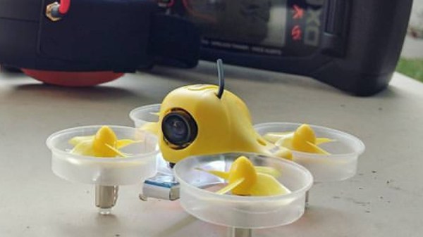
The fun is not however limited to team members. People in the audience will also be able to participate, by being invited to try their luck at bringing down a TinyWhoop that will periodically fly into the arena for a chance at their own prize. The ubiquitous cheap toy drone will be accessible through software, and would-be attackers are invited to register in advance to take a pop at it.
It looks as if DroneClash will be an unmissable event for anyone able to make it to the Netherlands on March 16th. We’ve mentioned it in past years, and we look forward to seeing what comes out of it this year too.
TinyWhoop header image: Dan Lundmark, (CC BY 2.0).