Machining is one of those fascinating fields that bridges the pre-scientific and scientific eras. As such, it has gone from a discipline full of home-spun acquired wisdom and crusty old superstitions to one of rigorously analyzed physics and crusty old superstitions.
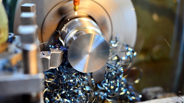
The earliest machinists figured out most of what you need to know just by jamming a tool bit into spinning stock and seeing what happens. Change a few things, and see what happens next. There is a kind of informal experimentation taking place here. People are gradually controlling for variables and getting better at the craft as they learn what seems to affect what. However, the difference between fumbling around and actually knowing something is controlling for one’s own biases in a reproducible and falsifiable way. It’s the only way to know for sure what is true, and we call this “science”. It also means being willing to let go of ideas you had because the double-blinded evidence clearly says they are wrong.
That last part is where human nature lets us down the most. We really want to believe things that confirm our preconceived notions about the world, justify our emotions, or make us feel better. The funny thing about science, though, is that it doesn’t care whether you believe in it or not. So go get your kids vaccinated, and up your machining game with scientific precision. Let’s take a look.