When it comes to choice of metals that can be melted in the home foundry, it’s a little like [Henry Ford]’s famous quip: you can melt any metal you want, as long as it’s aluminum. Not that there’s anything wrong with that; there’s a lot you can accomplish by casting aluminum. But imagine what you could accomplish by recycling cast iron instead.
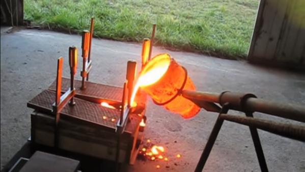
It looks like [luckygen1001] knows a thing or two about slinging hot metal around. The video below shows a fairly expansive shop and some pretty unique tools he uses to recycle cast iron; we were especially impressed with the rig he uses to handle the glowing crucibles from a respectful distance. The cast iron comes from a cheap and abundant source: car disc brake rotors. Usually available free for the asking at the local brake shop, he scores them with an angle grinder and busts them into manageable chunks with a hammer before committing them to the flames. The furnace itself is quite a thing, running on a mixture of diesel and waste motor oil and sounding for all the world like a jet engine starting up. [luckygen1001] had to play with the melt, adding lumps of ferrosilicon alloy to get a cast iron with better machining properties than the original rotors. It’s an interesting lesson in metallurgy, as well as a graphic example of how not to make a flask for molding cast iron.
Cast iron from the home shop opens up a lot of possibilities. A homemade cast aluminum lathe is one thing, but one with cast iron parts would be even better. And if you use a lot of brake rotors for your homebrew cast iron lathe, it might require special handling.
Continue reading “Move Over Aluminum: Cast Iron For The Home Foundry”