Laser cutters are becoming more garage-accessible with overseas imports, but plenty of us still need to drop in on the college campus or makerspace to get our cuts. Having a laser onsite is a nice touch, but having a rotary axis is almost unheard of. These nifty add-ons enable your laser to cut and engrave radially symmetric parts. Their pricetags usually fall in the hundred-to-thousand dollar price range, so while that might stop us there’s nothing holding us back from building our own!
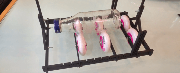
That’s exactly what both [Cesar] and [Russ] did with two homebrew designs built from scraps, and the results look comparable to the professional default. The design itself is simple, yet dead clever. The carriage straps directly onto the x-axis such that its motion is rigidly connected to it. The wheels on the bottom play a dual role. First, they let the carriage slide smoothly with the y-axis motion. They also support the object-to-be-engraved and convert the wheel rotation from the y-axis movement into rotation of the object. There’s one drawback here in that the diameter of the object-to-be-engraved affects the angle of rotation, but we’ve never been ashamed to do a little work with θ = s/r.
[Cesar] gets the credit for putting this hack out for the world to see, but [Russ] also get’s a big thanks for putting out a downloadable file of his carriage. It’s a testament to how sharing a thought can inspire us to iterate on better designs that they world can enjoy.
Rolling fourth-axes aren’t anything new on these pages, but they’re certainly rare! If your hungry for more rolling axis goodness, have a look at [Perry’s] router modifications.