As a community has grown up around the 8-bit microcomputers of the 1980s, there have been some beautifully crafted rebuilds of classic machines to take advantage of newer hardware or to interface to peripherals such as keyboards or displays that were unavailable at the time. Often these have taken the form of small boards, or boards that are designed to follow the form factor of the original machine, and fit in an original case.
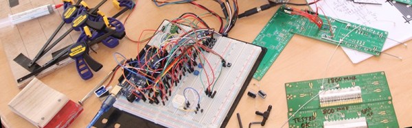
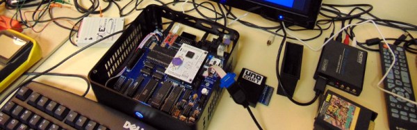
[mytekcontrols] has taken a different tack with his Atari 800 build, he’s produced an Atari clone designed to take the most popular upgrade boards produced by the 8-bit Atari community, as daughter boards. And he’s followed an existing form factor, though it’s not one from the Atari world. Instead, he’s made it as a mini-ITX motherboard of the type you may well be familiar with from the world of PCs.
He’s calling it the 1088XEL, because with a popular 1MB upgrade board fitted it boasts a generous 1088k of memory. It sports the original five Atari LSI chips, and manages the task without resorting to surface-mount construction.
The forum thread linked above is a long one that makes for a fascinating read as it deals in depth with the design of an 8-bit micro clone. But if you want to skip straight to the hardware, start at about page 13.
We’ve had more than one 8-bit Atari on these pages over the years. Most memorable though is probably this laptop.
Thanks [Lenore Underwood].