In case you are still wondering about the SHA-1 being broken and if someone is going to be spending hundreds of thousands of dollars to create a fake Certificate Authority and sniff your OkCupid credentials, don’t worry. Why spend so much money when your credentials are being cached by search engines?… Wait, what?
A serious combination of bugs, dubbed Cloudbleed by [Tavis Ormandy], lead to uninitialized memory being present in the response generated by the reverse proxies and leaked to the requester. Since these reverse proxies are shared between Cloudflare clients, this makes the problem even worst, since random data from random clients was leaking. It’s sort of like Heartbleed for HTTP requests. The seriousness of the issue can be fully appreciated in [Tavis] words:
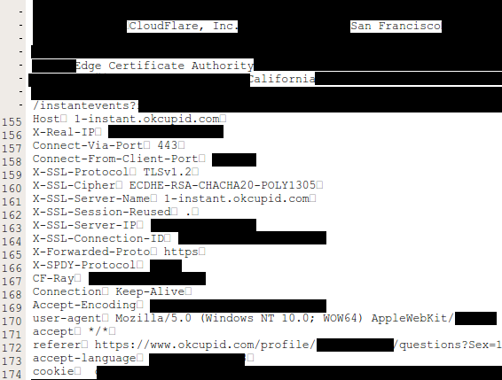
“The examples we’re finding are so bad, I cancelled some weekend plans to go into the office on Sunday to help build some tools to cleanup. I’ve informed cloudflare what I’m working on. I’m finding private messages from major dating sites, full messages from a well-known chat service, online password manager data, frames from adult video sites, hotel bookings. We’re talking full https requests, client IP addresses, full responses, cookies, passwords, keys, data, everything.”
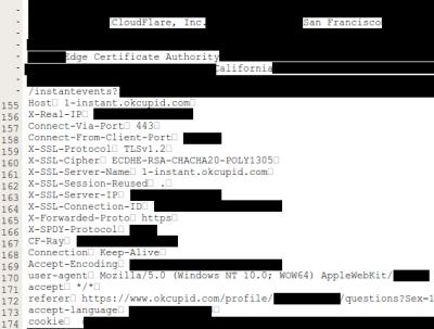 According to Cloudflare, the leakage can include HTTP headers, chunks of POST data (perhaps containing passwords), JSON for API calls, URI parameters, cookies and other sensitive information used for authentication (such as API keys and OAuth tokens). An HTTP request to a Cloudflare web site that was vulnerable could reveal information from other unrelated Cloudflare sites.
Adding to this problem, search engines and any other bot that roams free on the Internet, could have randomly downloaded this data. Cloudflare released a detailed incident report explaining all the technicalities of what happened and how they fixed it. It was a very quick incident response with initial mitigation in under 47 minutes. The deployment of the fix was also quite fast. Still, while reading the report, a sense that Cloudflare downplayed this issue remains. According to Cloudflare, the earliest date that this problem could have started is 2016-09-22 and the leak went on until 2017-02-18, five months, give or take.
Just to reassure the readers and not be alarmist, there is no evidence of anyone having exploiting what happened. Before public exposure, Cloudflare worked in proximity with search engines companies to ensure memory was scrubbed from search engine caches from a list of 161 domains they had identified. They also report that Cloudflare has searched the web (!), in sites like Pastebin, for signs of leaks and found none.
On the other hand, it might be very well impossible to know for sure if anyone has a chunk of this data cached away somewhere in the aether. It’s impossible to know. What we would really like to know is: does [Tavis] get the t-shirt or not?