Welcome back to the final chapter in our journey exploring two-stage tentacle mechanisms. This is where we arm you with the tools and techniques to get one of these cretins alive-and-kicking in your livingroom. In this last installment, I’ll guide us through the steps of building our very own tentacle and controller identical to one we’ve been discussing in the last few weeks. As promised, this post comes with a few bonuses:
Design Files
- The Almighty Bill-o’-Materials
- Vector Drawings for laser cutting
- DXF files pre-offset (0.003″)
- DXF files original
- STL Models for 3D Printing
- Original Tentacle CAD Model Files
- Original Controller CAD Model Files
Depending on your situation, some design files may be more important than others. If you just want to get parts made, odds are good that you can simply cut the pre-offset DXFs from the right plate thicknesses and get rolling. Of course, if you need to tune the files for a laser with a slightly different beam diameter, I’ve included the original DXFs for good measure. For the heavy-hitters, I’ve also included the original files if there’s something about this design that just deserves a tweak or two. Have at it! (And, of course, let us know how you improve it!)
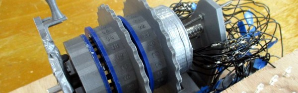
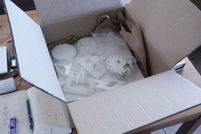
Ok, now that we’ve got the parts on-hand in a pile of pieces,let’s walk through the last-mile tweaks to making this puppet work: assembly and tuning. At this point, we’ve got a collection of parts, some laser-cut, some off the shelf. Now it’s time to string them together.
Continue reading “Two-Stage Tentacle Mechanisms Part III: Putting It All Together”