Sun On The Run: Diving Into Solar With A Mobile PV System

For obvious reasons, there has been a lot of interest in small-scale residential solar power systems lately. Even in my neck of the woods, where the sun doesn’t shine much from October to April, solar arrays are sprouting up on rooftops in a lot of local neighborhoods. And it’s not just here in suburbia; drive a little way out into the country or spend some time looking around in Google maps and it won’t take long to spy a sizable array of PV panels sitting in a field next to someone’s ranch house or barn.

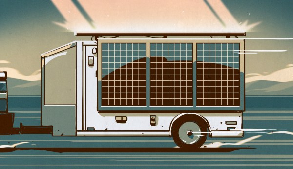
Solar has gotten to the point where the expense of an installation is no longer a serious barrier to entry, at least if you’re willing to put in a little sweat equity and not farm the project out to a contractor. Doing it yourself requires some specialized tools and knowledge, though, over and above your standard suite of DIY skills. So, in the spirit of sharing hard-won knowledge, I decided to take the somewhat unusual step of writing up one of my personal projects, which has been in progress for a couple of years now and resulted in a solar power system that isn’t on a rooftop or a ground-mounted array at all, but rather is completely mobile: my solar trailer.

Continue reading “Sun On The Run: Diving Into Solar With A Mobile PV System”

Ask Hackaday: What Do You Do When You Can’t Solder?

Ah, soldering. It’s great for sticking surface mount parts to a PCB, and it’s really great for holding component legs in a plated through-hole. It also does a pretty great job of holding two spliced wires together.

With that said, it can be a bit of a fussy process. There are all manner of YouTube videos and image tutorials on the “properest” way to achieve this job. Maybe it’s the classic Lineman’s Splice, maybe it’s some NASA-approved method, or maybe it’s one of those ridiculous ones where you braid all the copper strands together, solder it all up, and then realize you’ve forgotten to put the heat shrink on first.

Sure, soldering’s all well and good. But what about some of the other ways to join a pair of wires?

Continue reading “Ask Hackaday: What Do You Do When You Can’t Solder?”

PCIe For Hackers: External PCIe And OCuLink

We’ve seen a lot of PCIe hacks on Hackaday, and a fair few of them boil down to hackers pulling PCIe somewhere it wasn’t meant to be. Today, we routinely can find PCIe x1, x2 and x4 links sitting around in our tech, thanks to the proliferation of things like NVMe SSDs, and powerful cheap SoCs that make PCIe appear at your fingertips.

In the PCIe For Hackers series, we’ve talked about PCIe and how cool it is, all the benefits it has for hackers, gave you layout and interconnection rules, and even went into things like PCIe switches and bifurcation. However, there’s one topic we didn’t touch much upon, and that’s external PCIe links.

Today, I’d like to tell you about OCuLink – a standard that hackers might not yet know as an option whenever we need to pull PCIe outside of your project box, currently becoming all that more popular in eGPU space. Essentially, OCuLink is to PCIe is what eSATA is to SATA, and if you want to do an eGPU or an external “PCIe socket”, OCuLink could work wonders for you.

Respectable Capabilities

Just like any high-speed standard, PCIe has some tight requirements when things get fast. Even though PCIe is known to be not as sensitive to lower-quality links due to its link training and generation downgrade abilities, at higher link speeds, even through-hole vs SMD sockets can make a difference. So, if you want to go high-throughput, you want proper cabling and connectors, intended for out-of-chassis use – and OCuLink gives you all of this, at a low price.

Continue reading “PCIe For Hackers: External PCIe And OCuLink”

The Minimum Required For A Film Camera

Film cameras can be complex and exquisitely-crafted masterpieces of analogue technology. But at their very simplest they need be little more than a light-proof box with a piece of film at the back of it, and some kind of lens or pinhole with a shutter. [ChickenCrimpy] adds the most basic of 35 mm cartridge to create what he calls the Minimum Viable Camera. It’s a half-frame 35 mm pinhole film camera with the simplest possible construction.

A grainy B&W picture of a bird perched on a railing
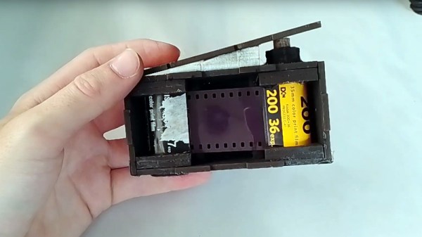
It can be built from almost any flat light-proof 3 mm thick stock, though something that you can run through a laser cutter is probably ideal. Once snapped together to make to box-like structure, tape is added along the joins for light-proofing. The film is reeled from a full 35 mm cartridge to an empty one, and cranked back frame-by-frame by means of a wooden key that engages with the spindle.

There’s no lens, instead this is a pinhole camera, and the shutter is a piece of the stock held on the front of the camera with bolts and butterfly nuts. Taking a photo is as simple as pointing the device at the subject and lifting the shutter away for a few seconds. There’s a video overview for the project which we’ve placed below the break.

It’s true that this camera needs a moment in the darkroom to load, but we like its extreme simplicity and the ethereal and grainy pictures it produces. If you fancy an introduction to 35 mm photography you could definitely do worse.

Continue reading “The Minimum Required For A Film Camera”

Using Industrial CT To Examine A $129 USB Cable

What in the world could possibly justify charging $129 for a USB cable? And is such a cable any better than a $10 Amazon Basics cable?

To answer that question, [Jon Bruner] fired up an industrial CT scanner to look inside various cables (Nitter), with interesting results. It perhaps comes as little surprise that the premium cable is an Apple Thunderbolt 4 Pro USB-C cable, which sports 40 Gb/s transfer rates and can deliver 100 Watts of power to a device. And it turns out there’s a lot going on with this cable from an engineering and industrial design perspective. The connector shell has a very compact and extremely complex PCB assembly inside it, with a ton of SMD components and at least one BGA chip. The PCB itself is a marvel, with nine layers, a maze of blind and buried vias, and wiggle traces to balance propagation delays. The cable itself contains 20 wires, ten of which are shielded coax, and everything is firmly anchored to a stainless steel shell inside the plastic connector body.

By way of comparison, [Jon] also looked under the hood at more affordable alternatives. None were close to the same level of engineering as the Apple cable, ranging as they did from a tenth to a mere 1/32nd of the price. While none of the cables contained such a complex PCB, the Amazon Basics cable seemed the best of the bunch, with twelve wires, decent shielding, and a sturdy crimped strain relief. The other cables — well, when you’re buying a $3 cable, you get what you pay for. But does that make the Apple cable worth the expense? That’s for the buyer to decide, but at least now we know there’s something in there aside from Apple’s marketing hype.

We’ve seen these industrial CT scanners used by none other than [Ken Shirriff] and [Curious Marc] to reverse engineer Apollo-era artifacts. If you want a closer look at the instrument itself, check out the video below

Continue reading “Using Industrial CT To Examine A $129 USB Cable”

Learning About Capacitors By Rolling Your Own Electrolytics

Ever wonder what’s inside an electrolytic capacitor? Many of us don’t, having had at least a partial glimpse inside after failure of the cap due to old age or crossed polarity. The rest of us will have to rely on this behind-the-scenes demo to find out what’s inside those little aluminum cans.

Perhaps unsurprisingly, it’s more aluminum, at least for the electrolytics [Denki Otaku] rolled himself at the Nippon Chemi-Con R&D labs. Interestingly, both the anode and cathode start as identical strips of aluminum foil preprocessed with proprietary solutions to remove any oils and existing oxide layers. The strips then undergo electrolytic acid etching to create pits to greatly increase their surface area. The anode strips then get anodized in a solution of ammonium adipate, an organic acid that creates a thin aluminum oxide layer on the strip. It’s this oxide layer that actually acts as the dielectric in electrolytic capacitors, not the paper separator between the anode and cathode strips.

Winding the foils together with the paper separator is pretty straightforward, but there are some neat tricks even at the non-production level demonstrated here. Attachment of lead wires to the foil is through a punch and crimp operation, and winding the paper-foil sandwich is actually quite fussy, at least when done manually. No details are given on the composition of the electrolyte other than it contains a solvent and an organic acid. [Denki] took this as an invitation to bring along his own electrolyte: a bottle of Coke. The little jelly rolls get impregnated with electrolyte under vacuum, put into aluminum cans, crimped closed, and covered with a heat-shrink sleeve. Under test, [Denki]’s hand-rolled caps performed very well. Even the Coke-filled caps more or less hit the spec on capacitance; sadly, their ESR was way out of whack compared to the conventional electrolyte.

There are plenty more details in the video below, although you’ll have to pardon the AI voiceover as it tries to decide how to say words like “anode” and “dielectric”; it’s a small price to pay for such an interesting video. It’s a much-appreciated look at an area of the industry that few of us get to see in detail.

Continue reading “Learning About Capacitors By Rolling Your Own Electrolytics”

Hackaday Links Column Banner

Hackaday Links: July 2, 2023

Members of Pixelbar woke up to shocking news on Wednesday morning this week as they learned that a fire had destroyed the building housing their Rotterdam hackerspace. Pictures of the fire are pretty dramatic and show the entire building ablaze. We’re not familiar with Pixelbar specifically, but most hackerspaces seem to share space with other businesses in repurposed warehouses and other industrial buildings, and it looks like that was the case here. Local coverage doesn’t indicate that a cause has been determined, but they do say that “large batches of wood” were stored in or near the structure, which likely contributed to the dramatic display. There don’t seem to be reports of injuries to civilians or first responders, so that’s a blessing, but Pixelbar seems to have been completely destroyed. If you’re in a position to help, check out their GoFundMe page. As our own Jenny List, who currently lives in The Netherlands, points out, spaces suitable for housing a hackerspace are hard to come by in a city like Rotterdam, which is the busiest port in Europe. That means Pixelbar members will be competing for space with businesses that have far deeper pockets, so anything you can donate will likely go a long way toward rebuilding.

Continue reading “Hackaday Links: July 2, 2023”