We saw a huge outpouring of builds for the the Hackaday Sci-Fi Contest and it’s now time to reveal the winners. With 84 great themed projects submitted, the judges had a tough task to pull out the most impressive both in terms of creativity and execution.
Here are our four winners. Two come from the Stargate universe. One is a cuddly yet horrifying character of unknown origin but unarguably Sci-Fi. The other is the best use of a bowling ball we’ve seen so far.
Grand Prize
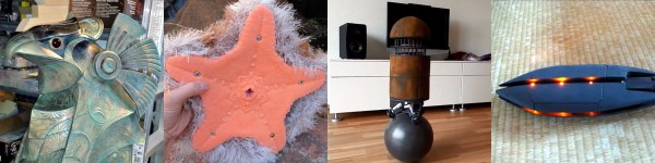
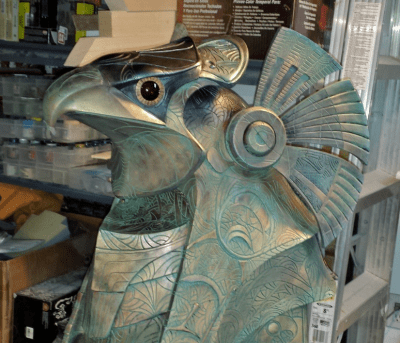 The grand prize goes to [Jerome Kelty] with Animatronic Stargate Helmet. [Jerome] has built a replica prop that looks like it just came out of a Hollywood shop. It’s almost a shame that this helmet won’t be worn on film – though it certainly could be. If you remember the film and the television show, these helmets have quite a bit of articulation. The head can pan and tilt. The eyes glow, as well as have irises which expand and contract. The “wings” also open and close in a particular way.
[Jerome] built the mechanics for this helmet. He used radio control servos to move the head, with the help of some hardware from ServoCity. Most of the metalwork was built in his own shop. Everything is controlled from a standard R/C transmitter, much like the original show. [Jerome] is taking home a Rigol DS1054Z 4 Channel 50 MHz scope.
First Prize
 First prize goes to [Christine] with
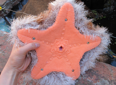
Starfish Cat: Your Lovecraftian Furby-like Friend. Starfish Cat is one of those odd projects that finds itself right on the edge of the uncanny valley. We are equal parts intrigued and creeped out by this… thing. The bottom is all starfish, with a rubber base poured into a 3D printed mold. The top though, is more cat-like, with soft fur and ears. 5 claws hide under the fur, ready to grab you.
Starfish Cat detects body heat with 5 bottom mounted PIR sensors. The sensors are read by the particle photon which acts as its brain. When heat is detected, Starfish Cat activates its claws, and also blows or sucks air through its… uh… mouth hole. [Christine] is taking home a Monoprice Maker Select Mini 3D printer.
Click past the break to see the rest of the winners
Continue reading “Starfish Cat, Bowling Ball Bot, And Stargate All Claim Prizes” →