YOLO can mean many things, but in the context of [be_riddickulous]’s AI Talking Robot Dinosaur it refers to the “You Only Look Once” YOLOv11 object-detection algorithm by Ultralytics, the method by which this adorable dino recognizes colors and shapes to teach them to children.
If you’re new to using YOLO or object recognition more generally, [be_riddiculous]’s tutorial is not a bad place to get started. She goes through how many images you’ll need and what types to get the shape-and-color recognition needed for this project, as well as how to annotate them and train the model, either locally or in the cloud.
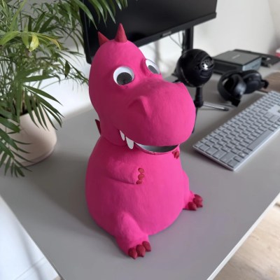 The project itself is an adorable paper-mache dinosaur with a servo-actuated mouth hiding some LEDs and a Raspberry Pi camera module to provide images. In operation, the dinosaur “talks” to children using pre-recorded voice lines, inviting them to play a game and put a specific shape, or shape of a specific color (or both) in its mouth. Then the aforementioned object detection (running on a laptop) goes “YOLO” and identifies the shape so the toy can provide feedback on the child’s choice via a speaker in the belly of the beast.
The link to the game code is currently not valid, but it looks like they used PyGame for the audio output code. A servo motor controls the mouth, but without that code it’s not entirely clear to us what it’s doing. We expect by the time you read this there’s good odds [be_riddickulous] will have fixed that link and you can see for yourself.
The only thing that holds this back from being a great toy to put in every Kindergarten class is the need to have a laptop close by to plug the webcam into. A Raspberry Pi 5 ought to have the horsepower to run YOLOv11, so with a little extra effort the whole thing could be standalone — there might even be room in there for batteries.We’ve had other hacks aimed at little ones, like a kid-friendly computer to relive the glory days of the school computer lab or one of the many iterations of the RFID jukebox idea. If you want to wow the kiddos with AI, perhaps take a look at this talking Santa plush.
Got a cool project, AI, kid-related, or otherwise? Don’t forget to toss us a tip!


