The advent of cheap and accessible one-off PCB production has been one of the pivotal moments for electronic experimenters during the last couple of decades. Perhaps a few still etch their own boards, but many hobbiest were happy to put away their ferric chloride. There’s another way to make PCBs, though, which is to mill them. [Tom Nixon] has made a small CNC mill for that purpose, and it’s rather beautiful.
In operation it’s a conventional XYZ mechanism, with a belt drive for the X and Y and a lead screw for the Z axis. The frame is made from aluminium extrusion, and the incidental parts such as the belt tensioners are 3D printed. The write-up is very comprehensive, and takes the reader through all the stages of construction. The brains of the outfit is a Creality 3D printer controller, but he acknowledges that it’s not the best for the job.
Until the release of Windows 11, the upgrade proposition for Windows operating systems was rather straightforward: you considered whether the current version of Windows on your system still fulfilled your needs and if the answer was ‘no’, you’d buy an upgrade disc. Although system requirements slowly crept up over time, it was likely that your PC could still run the newest-and-greatest Windows version. Even Windows 7 had a graphical fallback mode, just in case your PC’s video card was a potato incapable of handling the GPU-accelerated Aero Glass UI.
This makes a lot of sense, as the most demanding software on a PC are the applications, not the OS. Yet with Windows 11 a new ‘hard’ requirement was added that would flip this on its head: the Trusted Platform Module (TPM) is a security feature that has been around for many years, but never saw much use outside of certain business and government applications. In addition to this, Windows 11 only officially supports a limited number of CPUs, which risks turning many still very capable PCs into expensive paperweights.
Although the TPM and CPU requirements can be circumvented with some effort, this is not supported by Microsoft and raises the specter of a wave of capable PCs being trashed when Windows 10 reaches EOL starting this year.
Recently [Florin] was in the market for a basic uninterruptible power supply (UPS) to provide some peace of mind for the smart home equipment he had stashed around. Unfortunately, the cheap Serioux LD600LI unit he picked up left a bit to be desired, and required a bit of retrofitting.
To be fair, the issues that [Florin] ended up dealing with were less about the UPS’ capability to deal with these power issues, and more with the USB interface on the UPS. Initially the UPS seemed to communicate happily with HomeAssistant (HA) via Network UPS Tools over a generic USB protocol, after figuring out what device profile matched this re-branded generic UPS. That’s when HA began to constantly lose the connection with the UPS, risking its integration in the smart home setup.
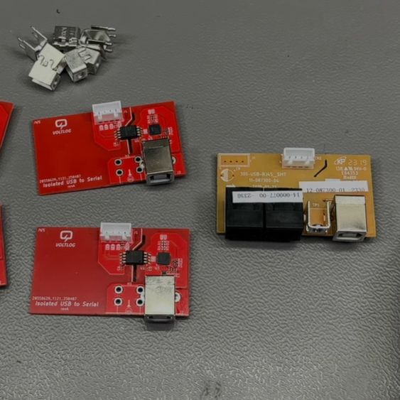
The old and new USB-serial boards side by side. (Credit: VoltLog, YouTube)
After tearing down the UPS to see what was going on, [Florin] found that it used a fairly generic USB-serial adapter featuring the common Cypress CY7C63310 family of low-speed USB controller. Apparently the firmware on this controller was simply not up to the task or poorly implemented, so a replacement was needed.
The process and implementation is covered in detail in the video. It’s quite straightforward, taking the 9600 baud serial link from the UPS’ main board and using a Silabs CP2102N USB-to-UART controller to create a virtual serial port on the USB side. These conversion boards have to be fully isolated, of course, which is where the HopeRF CMT8120 dual-channel digital isolator comes into play.
After assembly it almost fully worked, except that a Sonoff Zigbee controller in the smart home setup used the same Silabs controller, with thus the same USB PID/VID combo. Fortunately in Silabs AN721 it’s described how you can use an alternate PID (0xEA63) which fixed this issue until the next device with a CP2102N is installed
As it turns out, the cost of a $40 UPS is actually 10 hours of work and $61 in parts, although one cannot put a value on all the lessons learned here.
Some people really want a minimalist setup for their computing. In spite of his potentially worrisome housing situation, this was a priority for the man behind [Basically Homeless]: clean lines on the desk. Where does the PC go? You could get an all-in-one, sure, but those use laptop hardware and he wanted the good stuff. So he decided to hide the PC in the one place no one would ever think to look: inside his chair. (Youtube video, embedded below.)
This chair has very respectable specs: a Ryzen 7 9800XD, 64GB of ram and a RTX 4060 GPU, but you’d never know it. The secret is using 50 mm aluminum standoffs between the wooden base of the seat and the chair hardware to create room for low-profile everything. (The GPU is obviously lying sideways and connected with a PCIe riser cable, but even still, it needed a low-profile GPU.) This assemblage is further hidden 3D printed case that makes the fancy chair donated from [Basically Homeless]’s sponsor look basically stock, except for the cables coming out of it. It’s a very niche project, but if you happen to have the right chair, he does provide STLs on the free tier of his Patreon.
This is the first time we’ve seen a chair PC, but desk PCs are something we’ve covered more than once, so there’s obviously a demand to hide the electronics. It remains to be seen if hiding a PC in a chair will catch on, but if nothing else [Basically Homeless] will have a nice heated seat for winter. To bring this project to the next level of minimalism, we might suggest chording keyboards in the armrests, and perhaps a VR headset instead of a monitor.
Once a printed circuit board (PCB) has been assembled it’s rather hard to look inside of it, which can be problematic when you have e.g. a multilayer PCB of an (old) system that you really would like to dissect to take a look at the copper layers and other details that may be hidden inside, such as Easter eggs on inner layers. [Lorentio Brodeso]’s ‘LACED’ project offers one such method, using both chemical etching and a 5 Watt diode engraving laser to remove the soldermask, copper and FR4 fiberglass layers.
This project uses sodium hydroxide (NaOH) to dissolve the solder mask, followed by hydrogen chloride (HCl) and hydrogen peroxide (H2O2) to dissolve the copper in each layer. The engraving laser is used for the removing of the FR4 material. Despite the ‘LACED’ acronym standing for Laser-Controlled Etching and Delayering, the chemical method(s) and laser steps are performed independently from each other.
This makes it in a way a variation on the more traditional CNC-based method, as demonstrated by [mikeselectricstuff] (as shown in the top image) back in 2016, alongside the detailed setup video of how a multi-layer PCB was peeled back with enough resolution to make out each successive copper and fiberglass layer.
Google’s ChromeOS and associated hardware get a lot of praise for being easy to manage and for providing affordable hardware for school and other educational settings. It’s also undeniable that their locked-down nature forms a major obstacle and provides limited reusability.
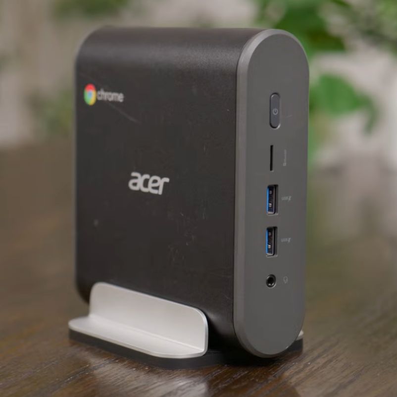
The Acer CXI3 in all its 8th-gen Intel Core i3 glory. (Credit: Hardware Haven, YouTube)
This is a nice mini PC, with modular SODIMM RAM, an NVMe storage M.2 slot as well as a slot for the WiFi card (or SATA adapter). After resetting the Chromebox to its default configuration and wiping the previous user, it ran at just a few watts idle at the desktop. As this is just a standard x86_64 PC, the only thing holding it back from booting non-ChromeOS software is the BIOS, which is where [MrChromebox]‘s exceedingly useful replacement BIOSes for supported systems come into play, with easy to follow instructions.
Reflashing the Acer CXI3 unit was as easy as removing the write-protect screw from the mainboard, running the Firmware Utility Script from a VT2 terminal (Ctrl+Alt+F2 on boot and chronos as login) and flashing either the RW_LEGACY or UEFI ROM depending on what is supported and desired. This particular Chromebox got the full UEFI treatment, and after upgrading the NVMe SSD, Debian-based Proxmox installed without a hitch. Interestingly, idle power dropped from 2.6 watts under ChromeOS to 1.6 watts under Proxmox.
If you have a Chromebox that’s supported by [MrChromebox], it’s worth taking a poke at, with some solutions allowing you to even dualboot ChromeOS and another OS if that’s your thing.
The iMac G3 is an absolute icon of industrial design, as (or perhaps more) era-defining than the Mac Classic before it. In the modern day, if your old iMac even boots, well, you can’t do much with it. [Rick Norcross] got a hold of a dead (hopefully irreparable) specimen, and stuffed a modern PC inside of it.
From the outside, it’s suprizingly hard to tell. Of course the CRT had to go, replaced with a 15″ ELO panel that fits well after being de-bezeled. (If its resolution is only 1024 x 768, well, it’s also only 15″, and that pixel density matches the case.) An M-ATX motherboard squeezes right in, above a modular PSU. Cooling comes from a 140 mm case fan placed under the original handle. Of course you can’t have an old Mac without a startup chime, and [Rick] obliges by including an Adafruit FX board wired to the internal speakers, set to chime on power-up while the PC components are booting.
These sorts of mods have proven controversial in the past– certainly there’s good reason to want to preserve aging hardware–but perhaps with this generation of iMac it won’t raise the same ire as when someone guts a Mac Classic. We’ve seen the same treatment given to a G4 iMac, but somehow the lamp doesn’t quite have the same place in our hearts as the redoubtable jellybean.