A Steady Hand Makes This Chip Work Again

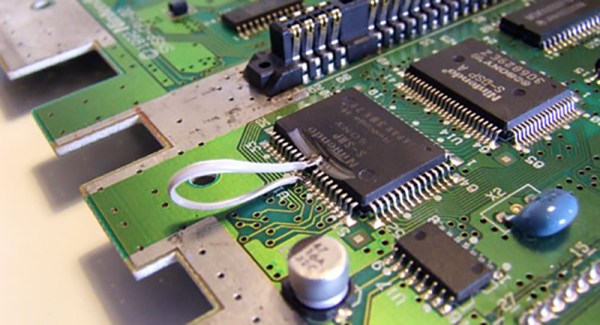
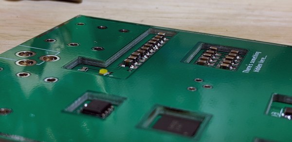
What do you do when you’re working with some vintage ICs and one of the tiny legs pops off? That’s what happened to [Kotomi] when working with an old Super Nintendo. A single lead for the sound chip just snapped off, leaving [Kotomi] one pin short of a working system (the Google Translatrix). This is something that can be fixed, provided you have a steady hand and a rotary tool that’s spinning at thousands of RPM.

Fixing this problem relies on a little bit of knowledge of how integrated circuits are built. There’s a small square of silicon in there, but this tiny die is bonded to a metal leadframe, which looks like the ribcage of a robotic centipede. This leadframe is covered in epoxy, the pins are bent down, and you have an IC. Removing just a tiny bit of epoxy grants access to the leadframe which you can then solder to. Don’t breathe the repair, it’s not pretty, but it does work.

While this technique makes use of a Dremel to break into the chewy nougat center of a vintage chip, and in some ways this could be called decapsulation, it really isn’t. We’ve seen people drop acid to get to the center of a chip and a really hot torch will get to the middle of a ceramic chip, but this technique is just accessing the lead frame of the IC. All ICs have a stamped (or photoetched) metal frame to which the silicone die is bonded. Running a Dremel against some epoxy doesn’t access the silicon, but it does grant access to the signals coming off the chip.

Oreo Construction: Hiding Your Components Inside The PCB

In recent months, the ability to hide components inside a circuit board has become an item of interest. We could trace this to the burgeoning badgelife movement, where engineers create beautiful works of electronic art. We can also attribute this interest to Bloomberg’s Big Hack, where Jordan Robertson and Michael Riley asserted Apple was the target of Chinese spying using components embedded inside a motherboard. The Big Hack story had legs, but so far no evidence of this hack’s existence has come to light, and the companies and governments involved have all issued denials that anything like this exists.

That said, embedding components inside a PCB is an interesting topic of discussion, and thanks to the dropping prices of PCB fabrication (this entire project cost $15 for the circuit boards), it’s now possible for hobbyists to experiment with the technique.

But first, it’s important to define what ‘stuffing components inside a piece of fiberglass’ is actually called. My research keeps coming back to the term ’embedded components’ which is utterly ungooglable, and a truly terrible name because ’embedded’ means something else entirely. You cannot call a PCB fabrication technique ’embedded components’ and expect people to find it on the Internet. For lack of a better term, I’m calling this ‘Oreo construction’, because of my predilection towards ‘stuf’, and because it needs to be called something. We’re all calling it ‘Oreo construction’ now, because the stuf is in the middle. This is how you do it with standard PCB design tools and cheap Chinese board houses.

Continue reading “Oreo Construction: Hiding Your Components Inside The PCB”

World’s Smallest LED Blinky

[Mike Harrison] is known for incredibly tiny soldering. Now he’s claiming a “world’s smallest” in the form of a stand-alone LED blinker, and we think he’s got the record.

He brought it along with him to Friday’s Beagleboard Bring-a-Hack, and we got a close look at the diminutive assembly. The project was dreamed up when [Mike] saw an announcement from Seiko about a new supercapacitor in a tiny package (likely the CPH3225A giving the blinky a footprint of 3.2 x 2.5 mm). With that in hand he added a PIC 10f322 microcontroller in a SOT23 package, an 0603 smoothing capacitor, and an SMD LED.

With such a tiny package, the trickiest part is figuring out how to charge that supercap. [Mike] used a drill and hand files to make a square hole in a CR2032 battery holder to serve as a jig. The bottom of the supercap rests against the battery as a pogo pin makes the second connection to a terminal on the side of his assembly. It charges quickly and will happily blink away for about six minutes after charging.

Mike set out to make two of these, but dropped the second supercap when at his workbench to be forever lost in the detritus common to every electronics workshop. When he first pulled it out at the meetup we were on a rooftop terrace and we were more than a bit concerned that this would just blow away. How do you begin to fabricate such a tiny assembly? He used UV cured epoxy to glue them together first, then somehow completed the soldering by hand!

Continue reading “World’s Smallest LED Blinky”

Underwater distributed sensor network

Open Source Underwater Distributed Sensor Network

One way to design an underwater monitoring device is to take inspiration from nature and emulate an underwater creature. [Michael Barton-Sweeney] is making devices in the shape of, and functioning somewhat like, clams for his open source underwater distributed sensor network.

Underwater distributed sensor network descent and ascent
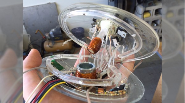
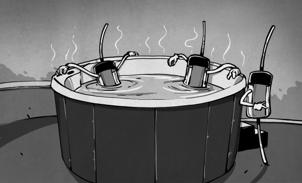
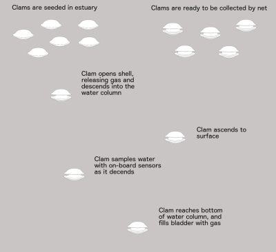
The clams contain the electronics, sensors, and means of descending and ascending within their shells. A bunch of them are dropped overboard on the surface. Their shells open, allowing the gas within to escape and they sink. As they descend they sample the water. When they reach the bottom, gas fills a bladder and they ascend back to the surface with their data where they’re collected in a net.

Thus far he’s made a few clams using acrylic for the shells which he’s blown himself. He soldered the electronics together free-form and gave them a conformal coating of epoxy. He’s also used a thermistor as a stand-in for other sensors and is already working on a saturometer, used for measuring the total dissolved gas (TDG) in the water. Knowing the TDG is useful for understanding and mitigating supersaturation of water which can lead to fish kills.

He’s also given a lot of thought into the materials used since some clams may not make it back up and would have to degrade or be benign where they rest. For example, he’s been using a lithium battery for now but would like to use copper on one shell and zinc on another to make a salt water battery, if he can make it produce enough power. He’s also considering using 3D printing since PLA is biodegradable. However, straight PLA could be subject to fouling by underwater organisms and would require cleaning, which would be time-consuming. PLA becomes soft when heated in a dishwasher and so he’s been looking into a PLA and calcium carbonate filament instead.

Check out his hackaday.io page where he talks about all these and more issues and feel free to make any suggestions.

Two-Cent Temperature Sensors

When they need to add temperature control to a project, many hackers reach for a K-type thermocouple for their high-temperature needs, or an integrated temperature-sensing IC when it doesn’t get that hot. The thermocouple relies on very small currents and extremely high gain, and you pretty much need a dedicated IC to read it, which can be expensive. The ICs aren’t as expensive, but they’re basically limited to boiling water. What do you do if you want to control a reflow oven?

There’s a cheaper way that spans a range between Antarctic winter and molten solder, and you’ve probably already got the parts on your shelf. Even if you don’t, it’s only going to run you an extra two cents, assuming that you’ve already got a microcontroller with an ADC in your project. The BOM: a plain-vanilla diode and a resistor.

I’ve been using diodes as temperature sensors in three projects over the last year: one is a coffee roaster that brings the beans up to 220 °C in hot air, another is a reflow hotplate that tops out around 210 °C, and the third is a toner-transfer iron that holds a very stable 130 °C. In all of these cases, I don’t really care about the actual numerical value of the temperature — all that matters is reproducibility — so I never bothered to calibrate anything. I thought I’d do it right for Hackaday, and try to push the humble diode to its limits for science.

What resulted was a PCB fire, test circuits desoldering themselves above 190 °C, temperature probes coming loose, and finally a broken ramekin and 200 °C peanut oil all over my desk. Fun times! On the other hand, I managed to get out enough data to calibrate some diodes, and the results are fantastic. The circuits under test included both best practices and the easiest thing that could possibly work, and the results are pretty close. This is definitely a technique that you want to have under your belt for most temperature ranges. The devil is in the details, of course, so read on!

Continue reading “Two-Cent Temperature Sensors”

Teardown: The Oregon Trail Handheld

If you were a school-age child in the 1980’s or 1990’s, you almost certainly played The Oregon Trail. Thanks to its vaguely educational nature, it was a staple of school computers until the early 2000’s, creating generations of fans. Now that those fans are old enough to have disposable incomes, we are naturally seeing a resurgence of The Oregon Trail merchandise to capitalize on one of humanity’s greatest weaknesses: nostalgia.

Enter the Target-exclusive The Oregon Trail handheld game. Priced at $24.99 USD and designed to look like the classic beige-box computers that everyone of a certain age remembers from “Computer Class”, it allows you to experience all the thrills of dying from dysentery on the go. Naturally there have been versions of the game for mobile devices in the past, but how is that going to help you when you want to make your peers at the coffee shop jealous?

But we’re not here to pass judgement on those who hold a special place for The Oregon Trail in their hearts. Surely, there’s worse things you could geek-out on than interactive early American history. No, you’re reading this post because somebody has put out a handheld PC-looking game system, complete with a simplified keyboard and you want to know what’s inside it. If there was ever a cheap game system that was begging to be infused with a Raspberry Pi and some retro PC games, this thing is it. Continue reading “Teardown: The Oregon Trail Handheld”

Building A Lightweight Softbox For Better Photography

If you want to take good photographs, you need good light. Luckily for us, you can get reels and reels of LEDs from China for pennies, power supplies are ubiquitous, and anyone can solder up a few LED strips. The missing piece of the puzzle is a good enclosure for all these LEDs, and a light diffuser.

[Eric Strebel] recently needed a softbox for some product shots, and came up with this very cheap, very good lighting solution. It’s made from aluminum so it should handle the rigors of photography, and it’s absolutely loaded with LEDs to get all that light on the subject.

The metal enclosure for this softbox is constructed from sheet aluminum that’s about 22 gauge, and folded on a brake press. This is just about the simplest project you can make with a brake and a sheet of metal, with the tabs of the enclosure held together with epoxy. The mounting for this box is simply magnets super glued to the back meant to attach to a track lighting fixture. The 5000 K LED strips are held onto the box with 3M Super 77 spray adhesive, and with that the only thing left to do is wire up all the LED strips in series.

But without some sort of diffuser, this is really only a metal box with some LEDs thrown into the mix. To get an even cast of light on his subject, [Eric] is using drawing vellum attached to the metal frame with white glue. The results are fairly striking, and this is an exceptionally light and sturdy softbox for photography.

Continue reading “Building A Lightweight Softbox For Better Photography”