A DIY 5V-3V Switching Converter In The Space Of A TO-220 Package

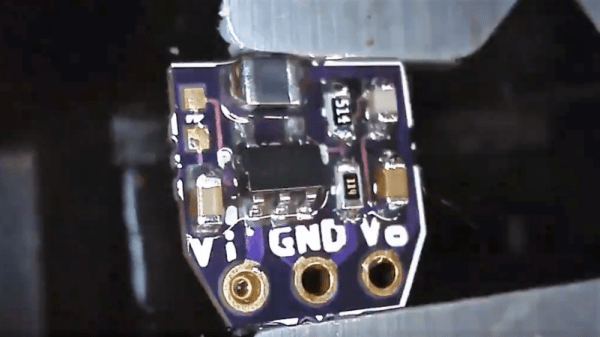
We’re suckers for miniaturization projects. Stuff anything into a small enough package and you’ve probably got our attention. Make that something both tiny and useful, like this 5-volt to 3.3-volt converter in a TO-220 sized package, and that’s something to get excited about. It’s a switch mode power supply that takes the same space as a traditional linear regulator.

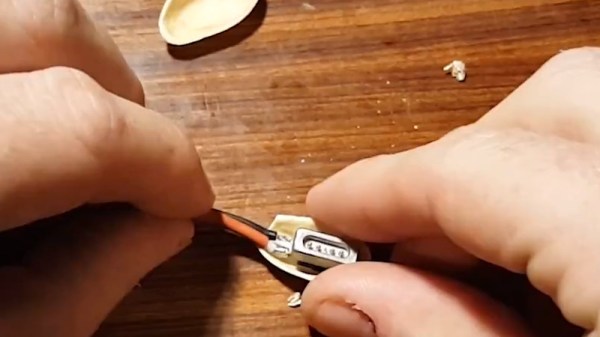
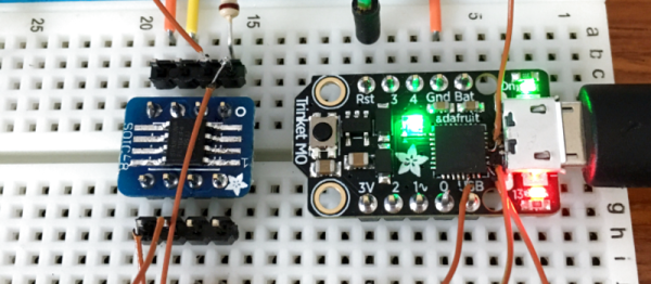
Granted, the heavy lifting in [Kevin Hubbard]’s diminutive buck converter is done by a PAM2305 DC-DC step-down converter chip which needs only a few supporting components. But the engineering [Kevin] put into this to squeeze everything onto a scrap of PCB 9-mm on a side is impressive. The largest passive on the board is the inductor in 0805. Everything else is in 0603, so you’ll be putting your SMD soldering skills to the test if you decide to make this. Check the video after the break for a speedrun through the hand soldering process.

The total BOM including the open-source PCB only runs a buck or two, and the end result is a supply with steady 750-mA output that can handle a 1-A surge for five seconds. We wonder if a small heatsink tab might not help that; along with some black epoxy potting, it would at least complete the TO-220 look.

[Kevin]’s Black Mesa Labs has a history of turning out interesting projects, from a legit video card for Arduino to a 100-watt hotplate for reflow work that’s the size of a silver dollar. We’re looking forward to whatever’s next — assuming we can see it.

Continue reading “A DIY 5V-3V Switching Converter In The Space Of A TO-220 Package”

Repairing A Macbook Charger… With A Pistachio Nut

Laptop chargers face a hard life. They’re repeatedly plugged and unplugged, coiled up, stuffed into bags, thrown around, and just generally treated fairly poorly. Combine this with fairly lightweight design and it’s not uncommon for a laptop charger to fail after a few years. It’s usually the connector that goes first. Such was the case when I found myself face to face with a failed Macbook charger, and figured it’d be a simple fix. Alas, I was wrong.

Unlike most PC manufacturers, who rely on the humble barrel jack and its readily available variants, Apple liked to use the Magsafe connector on its Macbook line. This connector has many benefits, such as quick release in the event someone trips over the cable, and the fact that it can be plugged in without regard to orientation. However, it’s not the easiest to fix. When the charger began failing, I noticed two symptoms. The first was that the charger would only function if the cable was held just so, in exactly the right orientation. The other, was that even when it would charge, the connector would become very hot. This led me to suspect an intermittent connection was the culprit, and it was quite a poor one at that; the high resistance leading to the heat issue.

It’s at this point with any other charger that you get out your trusty sidecutters, lop the end off, and tap away at Digikey to get a replacement part on the way. With Magsafe? No dice. Replacement parts simply aren’t available — a common problem with proprietary connectors. I endeavoured to fix the problem anyway. I began to strip away the metal shell around the back of the connector with my sidecutters, and eventually an angle grinder. A Dremel would have been the perfect tool for the job, actually, but I persevered regardless. After much consternation, I had the connector peeled back and was able to identify the problem.

Continue reading “Repairing A Macbook Charger… With A Pistachio Nut”

CNC’d MacBook Breathes Easy

Sick of his 2011 Macbook kicking its fans into overdrive every time the temperatures started to climb, [Arthur] decided to go with the nuclear option and cut some ventilation holes into the bottom of the machine’s aluminum case. But it just so happens that he had the patience and proper tools for the job, and the final result looks good enough that you might wonder why Apple didn’t do this to begin with.

After disassembling the machine, [Arthur] used double-sided tape and a block of scrap wood to secure the Macbook’s case to the CNC, and cut out some very slick looking vents over where the internal CPU cooler sits. With the addition of some fine mesh he found on McMaster-Carr, foreign objects (and fingers) are prevented from getting into the Mac and messing up all that Cupertino engineering.

[Arthur] tells us that the internal temperature of his Macbook would hit as high as 102 °C (~215 °F) under load before his modification, which certainly doesn’t sound like something we’d want sitting in our laps. With the addition of his vents however, he’s now seeing an idle temperature of 45 °C to 60 °C, and a max of 82 °C.

In the end, [Arthur] is happy with the results of his modification, but he’d change a few things if he was to do it again. He’s somewhat concerned about the fact that the mesh he used for the grill isn’t non-conductive (he’s using shims of card stock internally to make sure it doesn’t touch anything inside), and he’d prefer the peace of mind of having used epoxy to secure it all together rather than super-glue. That said, it works and hasn’t fallen apart yet; basically the hallmarks of a successful hack.

It’s worth noting that [Arthur] is not the first person to struggle with the Macbook’s propensity for cooking itself alive. A few years back we covered another user who added vents to their Macbook, but not before they were forced to reflow the whole board because some of the solder joints gave up in the heat.

Get Down To The Die Level With This Internal Chip Repair

Usually, repairing a device entails replacing a defective IC with a new one. But if you’ve got young eyes and haven’t had caffeine in a week, you can also repair a defective chip package rather than replace it.

There’s no description of the incident that resulted in the pins of the QFP chip being ablated, but it looks like a physical insult like a tool dropped on the pins. [rasminoj]’s repair consisted of carefully grinding away the epoxy cap to expose the internal traces leading away from the die and soldering a flexible cable with the same pitch between the die and the PCB pads.

This isn’t just about [rasminoj]’s next-level soldering skills, although we’ll admit you’ve got to be pretty handy with a Hakko to get the results shown here. What we’re impressed with is the wherewithal to attempt a repair that requires digging into the chip casing in the first place. Most service techs would order a new board, or at best solder in a new chip. But given that the chip sports a Fanuc logo, our bet is that it’s a custom chip that would be unreasonably expensive to replace, if it’s even still in production. Where there’s a skill, there’s a way.

Need more die-level repairs? Check out this iPhone CPU repair, or this repair on a laser-decapped chip.

[via r/electronics]

Friday Hack Chat: The Incredible BeagleBoard

Over the last year or so, the BeagleBoard community has seen some incredible pieces of hardware. The BeagleBone on a Chip — the Octavo OSD335x — is a complete computing system with DDR3, tons of GPIOs, Gigabit Ethernet, and those all-important PRUs stuffed into a single piece of epoxy studded with solder balls. This chip made it into tiny DIY PocketBones and now the official PocketBeagle is in stock in massive quantities at the usual electronic component distributors.

For this week’s Hack Chat, we’re talking about the BeagleBoard, BeagleBone, PocketBeagle, and PocketBone. [Jason Kridner], the co-founder of BeagleBoard and beagle wrangler, will be on hand to answer all your questions about the relevance of the Beagle platform today, the direction BeagleBoard is going, and the inner workings of what is probably the best way to blink LEDs in a Linux environment.

Topics for this Hack Chat will include the direction BeagleBoard is going, the communities involved with BeagleBoard, and how to get the most out of those precious programmable real-time units. As always, we’re taking questions from the community, submit them here.

As an extra special bonus, this week we’re giving away some hardware. Digi-Key has offered up a few PocketBeagle boards. If you have an idea for a project, put it on the discussion sheet and we’ll pick the coolest project and send someone a PocketBeagle.

join-hack-chat

Our Hack Chats are live community events on the Hackaday.io Hack Chat group messaging. This Hack Chat will be going down noon, Pacific time on Friday, October 13th. Wondering why the Brits were the first to settle on a single time zone when the US had a more extensive rail network and the longitude so time zones made sense? Here’s a time zone converter! Use that to ponder the mysteries of the universe.

Click that speech bubble to the right, and you’ll be taken directly to the Hack Chat group on Hackaday.io.

You don’t have to wait until Friday; join whenever you want and you can see what the community is talking about.

The Components Are INSIDE The Circuit Board

Through-hole assembly means bending leads on components and putting the leads through holes in the circuit board, then soldering them in place, and trimming the wires. That took up too much space and assembly time and labor, so the next step was surface mount, in which components are placed on top of the circuit board and then solder paste melts and solders the parts together. This made assembly much faster and cheaper and smaller.

Now we have embedded components, where in order to save even more, the components are embedded inside the circuit board itself. While this is not yet a technology that is available (or probably even desirable) for the Hackaday community, reading about it made my “holy cow!” hairs tingle, so here’s more on a new technology that has recently reached an availability level that more and more companies are finding acceptable, and a bit on some usable design techniques for saving space and components.

Continue reading “The Components Are INSIDE The Circuit Board”

Bodging On More Flash Memory

[Curmudegeoclast] found himself running out of flash memory on a Trinket M0 board, so he decided to epoxy and fly-wire a whopping 2 MB of extra flash on top of the original CPU.

We’ll just get our “kids these days” rant out of the way up front: the stock SAMD21 ARM chip has 256 kB (!) of flash to begin with, and is on a breakout board with only five GPIO pins, for a 51 kB / pin ratio! And now he’s adding 2 MB more? That’s madness. The stated reason for [Curmudegeoclast]’s exercise is MicroPython, which takes up a big chunk of flash just for the base language. We suspect that there’s also a fair amount of “wouldn’t it be neat?” in the mix as well. Whatever.

The hack is a classic. It starts off with sketchy wires soldered to pins and breadboarded up with a SOIC expander board. Following that proof of concept, some degree of structural integrity is brought to the proceedings by gluing the flash chip, dead-bug, on top of the microcontroller. We love the (0805?) SPI pullup resistor that was also point-to-point soldered into place. We would not be able to resist the temptation to entomb the whole thing in hot glue for “long-term” stability, but there are better options out there, too.

This hack takes a minimalist board, and super-sizes it, and for that, kudos. What would you stuff into 2 MB of free flash on a tiny little microcontroller? Any of you out there using MicroPython or CircuitPython care to comment on the flash memory demands? 256 kB should be enough for anyone.