Take This 3D-Print Post-Processing Method With A Grain Of Salt

There’s a lot of folklore around post-processing of prints from FDM printers. Proponents swear by their methods, which are generally intended to either strengthen the part or to improve its appearance, or both. But do they actually work?

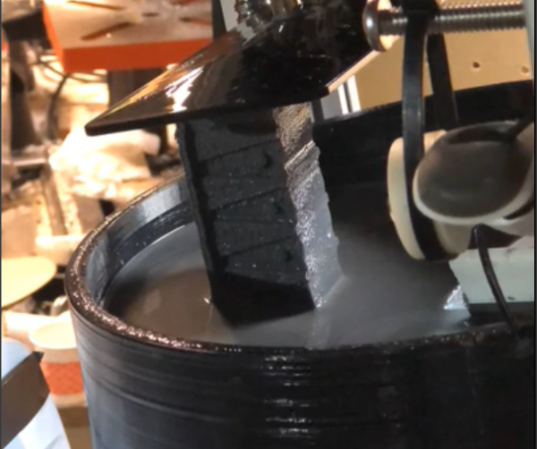
Knowing that a collection of anecdotes is no substitute for actual data, [Stefan] from CNC Kitchen has again performed some valuable experiments, this time testing the strength of parts that have been annealed in salt. This was a follow-up to his recent experiments with baking prints after entombing them in plaster, which yielded mixed results in terms of strength gains. Viewers commented that common salt makes a good medium for annealing prints, so he set about finding the right kind of salt. It turns out that the finer the grain, the better — powdery salt packs tighter and leaves little space for the softened plastic to flow — but that powdery salt is not easier to find. He ended up making his own by pulverizing table salt in a blender. He also had to play around with temperatures and times until coming up with a good process.

The results are impressive. PETG, ABS, and two varieties of PLA prints tested with force applied perpendicular to the print layers all showed marked increase in strength after breaking, to the point of nearly matching the strength of parts printed with the layers parallel to the stress. As with the plaster, parts were printed at 100% infill; a Benchy printed at 20% was notably unseaworthy after annealing. Surface finish on the annealed parts is an interesting combination of pitting with white residue — not unattractive but still a bit weird.

Salt annealing might be a bit cumbersome, but it’s a neat method to add to all the other post-processing tricks that people have come up with for their 3D prints. Continue reading “Take This 3D-Print Post-Processing Method With A Grain Of Salt”

Improved Flexible Build Plate For SLA Is Ready To Rock

The Elegoo Mars is an affordable SLA (resin-based) 3D printer, and there are probably few that have seen more mods and experimentation than [Jan Mrázek]’s machine. The final design of his DIY flexible build plate is a refinement of his original proof of concept, which proved a flexible build platform can be every bit as useful on an SLA printer as it is for FDM; instead of chiseling parts off a rigid build platform, simply pop the flexible steel sheet off the magnetic base and flex it slightly for a much easier part removal process. His original design worked, but had a few rough edges that have since been ironed out.

[Jan]’s magnetic build platform.
We love how [Jan] walks through all of the design elements and explains what worked and what didn’t. For example, originally he used a galvanized steel sheet which was easy enough to work with, but ended up not being a viable choice because once it’s bent, it stays bent. Spring steel is a much better material for a flexible build platform, but is harder for a hobbyist to cut.

Fortunately, it’s a simple job for any metal fabrication shop and [Jan] got a variety of thicknesses cut very cheaply. It turns out that the sweet spot is 0.3 mm (although 0.2 mm is a better choice for particularly fragile parts.) [Jan] also suggests cutting the sheet a few millimeters larger than the build platform; it’s much easier to peel the sheet off the magnetic base when one can get a fingertip under an edge, after all.

The magnetic base that the steel sheet sticks to is very simple: [Jan] converted a stock build platform by mounting an array of 20 x 20 x 1 mm magnets with 3M adhesive mounting tape. He was worried that resin might seep in between the magnets and cause a problem, perhaps even interfering with the adhesive; but so far it seems to be working very well. Resin is viscous enough that it never penetrates far into the gaps, and no effect on the adhesive has been observed so far.

Watch how easily parts are removed in the short video embedded below, in which [Jan] demonstrates his latest platform design.

Continue reading “Improved Flexible Build Plate For SLA Is Ready To Rock”

Polymer Networks Make Better 3D Prints

Biological machines such as human and animal bodies are quite incredible. Your body seamlessly incorporates materials as different as muscle, bone, and tendons into an integrated whole. Now Texas A&M researchers think they can imitate nature using polymer networks that have a tunable stiffness. As a bonus, similar to biological devices, the material spontaneously self-heals.

The trick relies on the Diels-Alder reaction which is a cycloaddition reaction of a conjugated diene to an alkene. Diels-Alder-based polymers or DAPs will bond together even when they have different physical characteristics and they undergo a reversible reaction to heat which offers shape-memory and healing capability.

Continue reading “Polymer Networks Make Better 3D Prints”

Adding Crush Ribs To 3D Printed Parts For A Better Press Fit

[Dan Royer] shared a tip about how to get a reliably tight fit between 3D printed parts and other hardware (like bearings, for example.) He suggests using crush ribs, a tried-and-true solution borrowed from the world of injection molding and repurposed with 3D printing in mind. Before we explain the solution, let’s first look at the problem a little more closely.

Imagine one wishes to press-fit a bearing into a hole. If that hole isn’t just the right size, the bearing won’t be held snugly. If the hole is a little too big, the bearing is loose. Too small, and the bearing won’t fit at all. Since a 0.1 mm difference can have a noticeable effect on how loose or snug a fit is, it’s important to get it right.

Crush rib locations highlighted with blue arrows.

For a 3D printed object, a hole designed with a diameter of 20 mm (for example) will come out slightly different when printed. The usual way around this is to adjust printer settings or modify the object until the magic combination that yields exactly the right outcome is found, also known as the Goldilocks approach. However, this means the 3D model only comes out right on a specific printer, which is a problem for a design that is meant to be shared. Since [Dan] works on robots with 3D printed elements, finding a solution to this problem was particularly important.

The solution he borrowed from the world of injection molding is to use crush ribs, which can be thought of as a set of very small standoffs that deform as a part is press-fit into them. Instead of a piece of hardware making contact with the entire inside surface of a hole, it makes contact only with the crush ribs. Press fitting a part into crush ribs is far easier (and more forgiving) than trying to get the entire mating surface exactly right.

Using crush ribs in this way is a bit of a hack since their original purpose in injection molding is somewhat different. Walls in injection-molded parts are rarely truly flat, because that makes them harder to eject from a mold. Surfaces therefore have a slight cant to them, which is called a draft. This slight angle means that press fitting parts becomes a problem, because any injection-molded hole will have slanted sides. The solution is crush ribs, which — unlike the walls — are modeled straight. The ribs are small enough that they don’t have an issue with sticking in the mold, and provide the mating surface that a press-fit piece of hardware requires. [Dan] has a short video about applying this technique to 3D printed objects, embedded below.

Continue reading “Adding Crush Ribs To 3D Printed Parts For A Better Press Fit”

Put That New Resin Printer To Work Making PCBs

With all the cool and useful parts you can whip up (relatively) quickly on a 3D printer, it’s a shame you can’t just print a PCB. Sure, ordering a PCB is quick, easy, and cheap, but being able to print one-offs would peg the needle on the instant gratification meter.

[Peter Liwyj] may just have come up with a method to do exactly that. His Instructables post goes into great detail about his method, which uses an Elegoo Mars resin printer and a couple of neat tricks. First, a properly cleaned board is placed copper-side down onto a blob of SLA resin sitting on the print bed. He tricks the printer into thinking the platform is all the way down for the first layer by interrupting the photosensor used to detect home. He lets the printer go through one layer of an STL file that contains his design, which polymerizes a thin layer of plastic onto the copper. The excess resin is wiped gently away and the board goes straight into a ferric chloride etching bath. The video below shows the whole process.

As simple as it sounds, it looks like it works really well. And [Peter] didn’t just stumble onto this method; he approached it systematically and found what works best. His tips incude using electrical tape as a spacer to lift the copper off the print surface slightly, cleaning the board with Scotchbrite rather than sandpaper, and not curing the resin after printing. His toolchain is a bit uncoventional — he used SketchUp to create the traces and exported the STL. But there are ways to convert Gerbers to STLs, so your favorite EDA package can probably fit in to the process too.

Don’t have a resin printer? Don’t worry — FDM printers can work too.

Continue reading “Put That New Resin Printer To Work Making PCBs”

FreeCAD Parametrics Made Simple

Simple drafting programs just let you draw like you’d use a pencil. But modern programs use parametric models to provide several benefits. One is that you can use parameters to change parts of your design and other parts will alter to take account of your changes. The other advantage is you can use one model for many similar but different designs. [Brodie Fairhall] has a nice video about how to use parameters in FreeCAD.

The nice thing about parameters is they don’t have to be just constants. You can put in formulae as well. For example, you could define one line as being twice as big as another line. You provide various constraints and parameters and FreeCAD works out the shape for you, keeping all the constraints and formulae satisfied.

Continue reading “FreeCAD Parametrics Made Simple”

The Prusa I3 MK3S And A Tale Of Two Sensors

When the Prusa i3 MK3 was released in 2017, it was marketed as being “bloody smart” thanks to the impressive number of sensors that had been packed into the printer. The update wasn’t really about improving print quality over the MK2, but rather to make the machine easier to use and more reliable. There was a system for resuming prints that had stopped during a power outage, a thermometer so the firmware could compensate against thermal drift in the inductive bed sensor, RPM detection on all of the cooling fans, and advanced Trinamic stepper drivers that could detect when the printer had slipped or gotten stuck.

The optical filament sensor of the Prusa i3 MK3.

But the most exciting upgrade of all was the new filament sensor. Using an optical encoder similar to what you’d find in a mouse, the Prusa i3 MK3 could detect when filament had been inserted into the extruder. This allowed the firmware to pause the print if the filament had run out, a feature that before this point was largely unheard of on consumer-grade desktop 3D printers. More than that, the optical encoder could also detect whether or not the filament was actually moving through the extruder.

In theory, this meant the MK3 could sense problems such as a jammed extruder or a tangle in the filament path that was keeping the spool from unrolling. Any other consumer 3D printer on the market would simply continue merrily along, not realizing that it wasn’t actually extruding any plastic. But the MK3 would be able to see that the filament had stalled and alert the user. The capabilities of the optical filament sensor represented a minor revolution in desktop 3D printing, and combined with the rest of the instrumentation in the MK3, promised to all but eradicate the heartbreak of failed prints.

Fast forward to February of 2019, and the announcement of the Prusa i3 MK3S. This relatively minor refresh of the printer collected up all the incremental tweaks that had been made during the production of the MK3, and didn’t really add any new features. Though it did delete one: the MK3S removed the optical encoder sensor used in the MK3, and with it the ability to sense filament movement. Users would have to decide if keeping the ability to detect clogs and tangles was worth giving up all of the other improvements offered by the update.

But why? What happened in those three years that made Prusa Research decide to abandon what promised to be a huge usability improvement for their flagship product? The answer is an interesting look at how even the cleverest of engineering solutions don’t always work as expected in the real-world.

Continue reading “The Prusa I3 MK3S And A Tale Of Two Sensors”