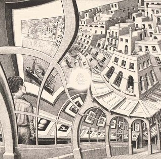
[Oliver Pett] loves creating automata; pieces of art whose physicality and motion come together to deliver something unique. [Oliver] also has a mission, and that mission is to complete the most complex automata he has ever attempted: The Archer. This automaton is a fully articulated figure designed to draw arrows from a quiver, nock them in a bow, draw back, and fire — all with recognizable technique and believable motions. Shoot for the moon, we say!
He’s documenting the process of creating The Archer in a series of videos, the latest of which dives deep into just how intricate and complex of a challenge it truly is as he designs the intricate cams required.
A digital, kinematic twin in Rhino 3D helps [Oliver] to choose key points and determine the cam profiles required to effect them smoothly.In simple automata rotational movement can be converted by linkages to create the required motions. But for more complicated automata (like the pen-wielding Maillardet Automaton), cams provide a way to turn rotational movement into something much more nuanced. While creating the automaton and designing appropriate joints and actuators is one thing, designing the cams — never mind coordinating them with one another — is quite another. It’s a task that rapidly cascades in complexity, especially in something as intricate as this.
[Oliver] turned to modern CAD software and after making a digital twin of The Archer he’s been using it to mathematically generate the cam paths required to create the desired movements and transitions, instead of relying on trial and error. This also lets him identify potential collisions or other errors before any metal is cut. The cams are aluminum, so the fewer false starts and dead ends, the better!
Not only is The Archer itself a beautiful piece of work-in-progress, seeing an automaton’s movements planned out in this way is a pretty interesting way to tackle the problem. We can’t wait to see the final result.
[James]’ Mechanical Organ of Dutch origin has been around longer than he has, but thanks to being rebuilt over the years and lovingly cared for, it delivers its unique performances just as well as it did back in the day. Even better, we’re treated to a good look at how it works.
The organ produces music by playing notes on embedded instruments, which are themselves operated by air pressure, with note arrangements read off what amounts to a very long punch card. [James] gives a great tour of this fantastic machine, so check it out in the video embedded below along with a couple of its performances.
[Teddy Warner]’s GPenT (Generative Pen-trained Transformer) project is a wall-mounted polargraph that makes plotter art, but there’s a whole lot more going on than one might think. This project was partly born from [Teddy]’s ideas about how to use aspects of machine learning in ways that were really never intended. What resulted is a wall-mounted pen plotter that offers a load of different ‘generators’ — ways to create line art — that range from procedural patterns, to image uploads, to the titular machine learning shenanigans.
There are loads of different ways to represent images with lines, and this project helps explore them.
Want to see the capabilities for yourself? There’s a publicly accessible version of the plotter interface that lets one play with the different generators. The public instance is not connected to a physical plotter, but one can still generate and preview plots, and download the resulting SVG file or G-code.
Most of the generators do not involve machine learning, but the unusual generative angle is well-represented by two of them: dcode and GPenT.
dcode is a diffusion model that, instead of converting a text prompt into an image, has been trained to convert text directly into G-code. It’s very much a square peg in a round hole. Visually it’s perhaps not the most exciting, but as a concept it’s fascinating.
The titular GPenT works like this: give it a scrap of text inspiration (a seed, if you will), and that becomes a combination of other generators and parameters, machine-selected and stacked with one another to produce a final composition. The results are unique, to say the least.
Once the generators make something, the framed and wall-mounted plotter turns it into physical lines on paper. Watch the system’s first plot happen in the video, embedded below under the page break.
This is a monster of a project representing a custom CNC pen plotter, a frame to hold it, and the whole software pipeline both for the CNC machine as well as generating what it plots. Of course, the journey involved a few false starts and dead ends, but they’re all pretty interesting. The plotter’s GitHub repository combined with [Teddy]’s write up has all the details one may need.
It’s also one of those years-in-the-making projects that ultimately got finished and, we think, doing so led to a bit of a sigh of relief on [Teddy]’s part. Most of us have unfinished projects, and if you have one that’s being a bit of a drag, we’d like to remind you that you don’t necessarily have to finish-finish a project to get it off your plate. We have some solid advice on how to (productively) let go.
Like many of us, [Tim]’s seen online videos of circuit sculptures containing illuminated LED filaments. Unlike most of us, however, he went a step further by using graph theory to design glowing structures made entirely of filaments.
The problem isn’t as straightforward as it might first appear: all the segments need to be illuminated, there should be as few powered junctions as possible, and to allow a single power supply voltage, all paths between powered junctions should have the same length. Ideally, all filaments would carry the same amount of current, but even if they don’t, the difference in brightness isn’t always noticeable. [Tim] found three ways to power these structures: direct current between fixed points, current supplied between alternating points so as to take different paths through the structure, and alternating current supplied between two fixed points (essentially, a glowing full-bridge rectifier).
To find workable structures, [Tim] represented circuits as directed graphs, with each junction being a vertex and each filament a directed edge, then developed filter criteria to find graphs corresponding to working circuits. In the case of power supplied from fixed points, the problem turned out to be equivalent to the edge-geodesic cover problem. Graphs that solve this problem are bipartite, which provided an effective filter criterion. The solutions this method found often had uneven brightness, so he also screened for circuits that could be decomposed into a set of paths that visit each edge exactly once – ensuring that each filament would receive the same current. He also found a set of conditions to identify circuits using rectifier-type alternating current driving, which you can see on the webpage he created to visualize the different possible structures.
We’ve seen some artistic illuminated circuit art before, some using LED filaments. This project doesn’t take exactly the same approach, but if you’re interested in more about graph theory and route planning, check out this article.
When it comes to electromagnetic waves, humans can really only directly perceive a very small part of the overall spectrum, which we call “visible light.” [rootkid] recently built an art piece that has perception far outside this range, turning invisible waves into a visible light sculpture.
The core of the device is the HackRF One. It’s a software defined radio (SDR) which can tune signals over a wide range, from 10 MHz all the way up to 6 GHz. [rootkid] decided to use the HackRF to listen in on transmissions on the 2.4 GHz and 5 GHz bands. This frequency range was chosen as this is where a lot of devices in the home tend to communicate—whether over WiFi, Bluetooth, or various other short-range radio standards.
The SDR is hooked up to a Raspberry Pi Zero, which is responsible for parsing the radio data and using it to drive the light show. As for the lights themselves, they consist of 64 filament LEDs bent into U-shapes over a custom machined metal backing plate. They’re controlled over I2C with custom driver PCBs designed by [rootkid]. The result is something that looks like a prop from some high-budget Hollywood sci-fi. It looks even better when the radio waves are popping and the lights are in action.
[Make Something] boasts he has made probably the fanciest picture frame you’ll ever see. He started with an original sign purchased on eBay and then made it to be bigger, brighter, and better. The frame is of solid walnut with back-lighting for the imagery all chasing that classic mid-century modern style. The backlit photo was taken the “hard way”, with an actual film camera and a road-trip to the picturesque site at Yellowstone. [Make Something] then developed the film himself in his home studio.
For the chimney [Make Something] used a new trick he learned in Autodesk Fusion: you take a photo of an object, convert to black and white, and then use the light/dark values to emboss or deboss a surface. To do this he took photos of the brick wall outside his shop and used that as the basis of the textured chimney he made with his 3D printer.
You’ve likely seen an X-cube, a dichroic prism used to split light into its constituent colours–you know, those fun little cubes you get when tearing apart a broken projector. Have you considered that the X-cube need not be a cube for its entire existence? [Matt] at “Matt’s Corner of Gem Cutting” on YouTube absolutely did, which is why he ground one into a 216-facet disco ball.
That’s the hack, really. He took something many of us have played with at our desks thinking “I should do something cool with this” and… did something cool with it that most of us lack the tools and especially skills to even consider. It’s not especially practical, but it is especially pretty. Art, in other words.
The shape he’s using is known specifically to gemologists as “Santa’s Little Helper II” though we’d probably describe it as a kind of isosphere. Faceting the cube is just a matter of grinding down the facets to create the isosphere, then polishing them to brilliance with increasingly finer grit. This is done one hemisphere at a time, so the other hemisphere can be safely held in place with the now-classic cyanoacrylate and baking soda composite. Yes, jewelers use that trick, too.
We were slightly worried when [Matt] dumped his finished disco ball in acetone to clean off the cyanoacrylate– we haven’t the foggiest idea what optical-quality glue is used to hold the four prisms of an X-cube together and were a little worried acetone might soften the joints. That turned out not to be an issue, and [Matt] now has the most eye-catching sun-catcher we think we’ve ever seen.