A Vintage Monitor Lives Again With A New Heart

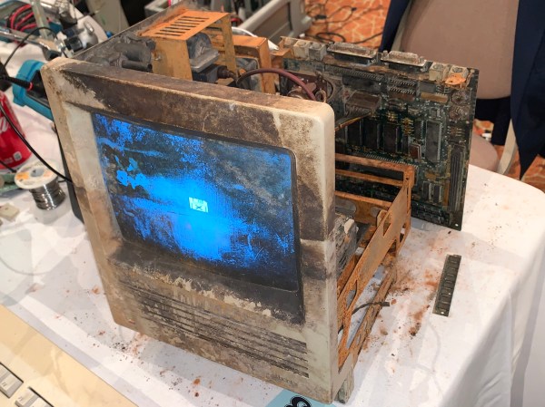
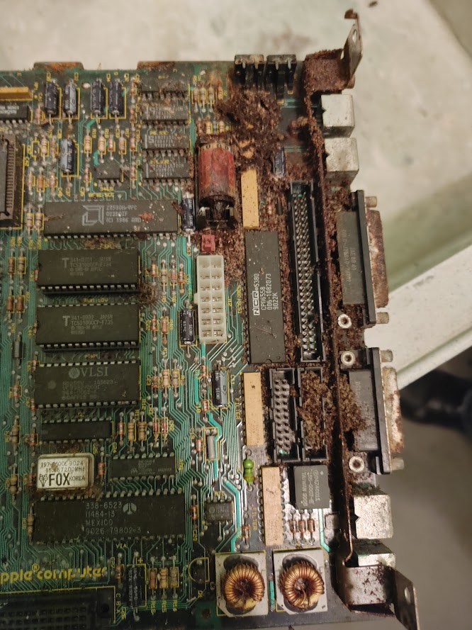
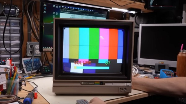
Aside from keeping decades-old consumer-grade computing hardware working, a major problem for many retrocomputing enthusiasts lies in doing the same for vintage monitors. Whether your screen is a domestic TV or a dedicated monitor, the heat and voltage stress of driving a CRT made these devices significantly less reliable than many of their modern-day counterparts. [Adrian’s Digital Basement] has a worn-out and broken Commodore 1701 monitor, which he’s brought back to life with a modern circuit board and a CRT transplant.

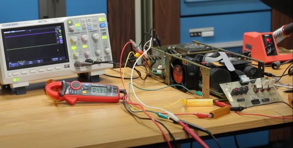
Following on from a previous project, he’s using a replacement board sold as a repair option for CRT TVs on AliExpress. The Commodore monitor has its board on a metal chassis which takes the replacement with a bit of modification. He doesn’t say where the new CRT came from, but we’re guessing it was a late model TV as CRTs made over the last few decades are more interchangeable than might be expected. There’s a moment of mild dodginess as he makes a voltage doubler to run the 220 V board from 120 V with a pair of large electrolytic capacitors hot glued in place, but otherwise it’s a success.

At the end of it all after some testing and set-up he has a Commodore monitor with a new heart and multi-standard support. Is it really a Commodore monitor though, or should it have been repaired? It’s a difficult one to answer, but we’d suggest that CRT monitor repair is less easy today than it used to be because many of the parts are now difficult to find. If it saves at least some of the original from the dumpster it’s better than doing nothing. We wonder how long these upgrades will remain possible as even with Chinese plants making these boards and a handful of CRT TVs still appearing on AliBaba it’s clear that CRTs are at the very end of their life.

Continue reading “A Vintage Monitor Lives Again With A New Heart”

Bringing An IBM Butterfly Laptop Back From The Dead

Among all the laptops produced over the last few decades, there is one which rises above the rest and which has retained an appeal long after its meager computing resources became obsolete. It’s the IBM 701c, the famous “Butterfly” laptop, whose fold-out keyboard still gives it star  quality, and [John Graham-Cumming] has documented the restoration of one from the tattered remains of two scrap examples.

The two laptops in question were someone else’s never-started project, and were in a sorry state. The flexible cables were in poor condition, and the 1990s Ni-MH batteries had leaked and damaged both circuits and case. We were unaware that NiMH leakage could damage plastic, but the parts of these machines were significantly damaged.

One had a working mainboard, the other a working modem card. One keyboard was in pretty bad shape, the other was complete. Of the pair there was a double super twisted nematic (DSTN) display and a more contemporary thin film transistor (TFT) panel. Be thankful if you have never had to use a DSTN laptop, as they were truly awful. From this pile of parts a working machine could be made, and with a new CMOS battery, that cable repair, and a repaint, he was ready. Or at least, as he says, ready for 1995.

This isn’t the first 701c restoration we’ve seen, and within reason, it’s even possible to give them a retro processor upgrade.

Crusty: The Story Of The Mac SE That Could

Retrocomputing often involves careful restorations, rare components, and white gloves.  This story involves none of those. This is the story of two people who sought to answer one of the greatest questions in the universe: What does it take to kill a Mac SE?

Crusty’s mainboard as found

The star of the show here is Crusty, a Mac SE that was found on the loading dock of a scrap company. It sat out in the weather for at least 6 months, complete with the original leaking lithium battery.

Enter [RadRacer203], who is friends with the owner of this particular scrap company. [RadRacer203] and picked up Crusty, along with a few other classic Macs. He brought these machines to VCF East 2021, where our other hero comes in. [CJ] is something of a magician with CRTs and analog electronics. Trained under [Sark] himself, [CJ] has mastered the 5-finger exploding capacitor technique.

The battery had eaten through the mainboard and even into the chassis. But after a thorough cleaning, the damn thing booted up. Crusty was born.

This Mac was a survivor. Much like Top Gear and their plucky Toyota Hilux, [RadRacer203] and [CJ] devised a plan to put Crusty to the test.

Click through the break for more!

Continue reading “Crusty: The Story Of The Mac SE That Could”

Writing And Running Atari 2600 Games In Your Browser

Here in 2024, writing new games for the venerable Atari 2600 game console is easier than ever, with plenty of emulators and toolchains to convert your code into ready-to-load ROMs. Yet what is easier than diving straight into 6502 assembly code without even having to download or set up a toolchain? That’s where [Henry Schmale]’s fully in-browser Atari IDE and associated emulator (using the Javatari project) comes into play.

As [Henry] explains in a blog post, the main goal was to get a project working in Emscripten, the LLVM-based toolchain to create WebAssembly binaries with. The target of this became DASM, the macro assembler for a range of 8-bit MPUs, including the 6502. In the blog post [Henry] describes the general procedure for how he compiled and integrated DASM, as part of creating the earlier linked Atari 2600.

In this IDE a number of example programs are provided, which can be selected, assembled and run in the integrated Javatari instance. Beyond this you can write your own custom 6502 ASM, of course, but at this point you may be interested in taking things further with the versatile Stella emulator that can even run on platforms which you’d be hard-pressed to get a browser running on, never mind Chromium.

Fixing A PDP-11/03 Power Supply Is Easy When You Understand It

After we last saw [David Lovett] of [Usagi Electric], he was knee-deep in trying to fix a DEC PDP-11/03 power supply, which fortunately led to a fixed PSU and a very happy PDP-11/23 system installed in the enclosure, as he covers in today’s video. Previously, we had covered his debugging attempt of this very much dead power supply, which had led [David] down many fruitless rabbitholes. By the time he was taking various components off the board to try and induce certain results, he threw in the towel and went back to the drawing board, assisted with many community comments.

The 5V rail on a DEC PDP-11/03 power supply. (Credit: David Lovett)

Much of the confusion came down to not really understanding how this PDP-11/03 PSU design works, which isn’t that crazy in hindsight, considering how quaint it is. Although [David] originally focused on the +5V rail, a small detail that was in the schematics is that the 5V rail is based around a 7805 that has its ground referenced to the -15V rail.

It is this 7805 that provides a linearly regulated 5V rail up till its current limit, at which point the control transistor gets biased sufficiently to start conducting, which eventually triggers the driver transistor that is responsible for driving the pass switch transistor. This then charges L2 from the unregulated supply, which is used effectively as a switching mode power supply until the current across the 7805 drops sufficiently that it becomes the primary 5V rail source again. This repeats at a kHz rate, making it more or less an SMPS as we know it today, but heavily reliant on the -15V rail as can be observed in the schematic. Continue reading “Fixing A PDP-11/03 Power Supply Is Easy When You Understand It”

640k Was Never Enough For Anyone: How DOS Broke Free

On modern desktop and laptop computers, there is rarely a need to think about memory. We all have many gigabytes of the stuff, and it’s just there. Our operating system does the heavy lifting of working out what goes where and what needs to be paged to disk, and we just get on with reading Hackaday, that noblest of computing pursuits. This was not always the case though, and for early PCs in particular the limitations of the 8086 processor gave the need for some significant gymnastics in search of an extra few kilobytes. [Julio Merion] has an interesting run-down of the DOS memory map, and how memory expansion happened on computers physically unable to see much of it.

The 8086 has a 20-bit address bus, giving it access to a maximum of 1 megabyte. When IBM made the PC they needed space for the BIOS, the display, and the various accessory ROMs intended to come with expansion cards. Thus they allocated a maximum 640k of the map for RAM, and many early machines shipped with much less than that. The quote from Bill Gates about 640k being enough for anyone is probably apocryphal, but it was pretty clear as the 1980s wore on that more would be needed. The post goes into how memory expansion worked, with a 64k page mapped to switchable RAM on a card, and touches on how DOS managed extended memory above 1 Mb on the later processors that supported it. We dimly remember there also being a device driver that would map the unused graphics memory as EMS when the graphics card was running in text mode, but such horrors are best left behind.

Of course, some of the tricks to boost RAM were nothing but snake oil.

8086 header: Thomas Nguyen, CC BY-SA 4.0

Erasing EEPROMs Isn’t Always As Easy As It Seems

When is 14 volts not actually 14 volts? Given [Anders Nielsen]’s recent struggles with erasing an old-school EEPROM, it’s when you really need it that things tend to go pear-shaped.

A little background is perhaps in order. [Anders] is working on a scratch-built programmer for ROMs to complement his 65uino project, which puts a complete 6502 computer into the footprint of an Arduino Uno. He wisely started the ROM programmer project at the beginning, which was to generate the correct voltages for programming. This turned out to be not as easy as you might think thanks to the solderless breadboard’s parasitic effects on the MIC2288 switching boost regulator he chose.

The video below is a continuation of the programmer build, which ends up being just as fraught as the first part. Being able to generate the programming voltages is one thing; getting them onto the right pins at the right time using nothing but the 5-volt GPIOs on a microcontroller is another. In true retro fashion, [Anders] tackled that problem with a pair of small-signal transistors, which seemed to work once the resistor values were sorted, at least when applying a 12-volt signal intended to show the ROM’s hard-coded manufacturer ID on the data bus.

But erasing the ROM, which requires 14 volts while the chip enable line is held high for 100 ms, proved a little trickier. Despite multiple tries, the ROM wouldn’t erase thanks to the 14-volt rail being dragged down to around 9 volts. [Anders] fixed that with a new base resistor on the driver, to increase the current and keep the voltage up where it needs to be. Just goes to show you that the data sheets don’t always tell the whole story.

We’ve been enjoying the unfolding story of this programmer, and we’re looking forward to the next installment.

Continue reading “Erasing EEPROMs Isn’t Always As Easy As It Seems”