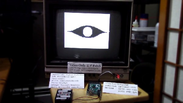
Building A Pocket Sized Arduino Oscilloscope

There’s little question that an oscilloscope is pretty much a must-have piece of equipment for the electronics hacker. It’s a critical piece of gear for reverse engineering devices and protocols, and luckily for us they’re as cheap as they’ve ever been. Even a fairly feature rich four channel scope such as the Rigol DS1054Z only costs about as much as a mid-range smartphone. But if that’s still a little too rich for your taste, and you’re willing to skimp on the features a bit, you can get a functional digital oscilloscope for little more than pocket change.

While there are a number of very cheap pocket digital storage oscilloscopes (DSOs) on the market, [Peter Balch] decided he’d rather spin up his own version using off-the-shelf components. Not only was it an excuse to deep dive on some interesting engineering challenges, but it ended up bringing the price even lower than turn-key models. Consisting of little more than an Arduino Nano and a OLED display, the cost comes out to less than $10 USD for a decent DSO that’s about the size of a matchbox.

But not a great one. [Peter] is very upfront about the limitations of this DIY pocket scope: it can’t hit very high sample rates, and the display isn’t really big enough to convey anything more than the basics. But if you’re doing some quick and dirty diagnostics in the field, that might be all you need. Especially since there’s a good chance you can build the thing out of parts from the junk bin.

Even if you’re not looking to build your own version of the Arduino-powered scope [Peter] describes, his write-up is still full of fascinating details and theory. He explains how his software approach is to disable all interrupts, and put the microcontroller into a tight polling loop to read data from the ADC as quickly as possible. It took some experimentation to find the proper prescaler value for the Atmega’s 16MHz clock, but in the end found he could get a usable (if somewhat noisy) output with a 1uS sample rate.

Unfortunately, the Arduino’s ADC leaves something to be desired in terms of input range. But with the addition of an LM358 dual op-amp, the Arduino scope gains some amplification so it can pick up signals down into the mV range. For completion’s sake, [Peter] included some useful features in the device’s firmware, such as a frequency counter, square wave signal source, and even a voltmeter. With the addition of a 3D printed case, this little gadget could be very handy to have in your mobile tool kit.

If you’d rather go the commercial route, Hackaday’s very own [Jenny List] has been reviewing a number of very affordable models such as the DSO Nano 3 and the JYE Tech DSO150 build-it-yourself kit.

[Thanks to BaldPower for the tip.]

Easy GUI Front Ends For Arduino, Rasberry Pi, And More With MyOpenLab

If you want to integrate a nice graphical interface with a microcontroller or single-board computer for a useful piece of custom equipment, how will you go about it? MyOpenLab is a platform that makes it easy to design virtual interfaces your electronic builds. If you want controls and readouts for Arduino, Raspberry Pi, Android, or anything with a serial port, this is worth a try.

MyOpenLab reminds me of LabView. Not so much modern LabView with all of its add-ons and extras, but LabView back when it did just a few things but did them really well. The open source MyOpenLab project has been around for a while. The website and documentation are not in English, which may have kept some people from giving it a try, but the software itself is available in German, English, and Spanish. I took the plunge and found the language barrier didn’t cause me trouble.

As an example of what you can do, image you want to build a custom bench tool. You build virtual device (they call it a “VirtualMachine”) that uses your computer as the control panel and readout, and your electronic project as the physical interface. In myOpenLab your device will consist of two parts: a diagram and a front panel. Some things only live on the diagram, like a timer or a connection to an Arduino. But some things live on both like switches, LEDs, graphs, and so on. You can connect all the little boxes together to build up applications. They can stand alone, but the power comes in being able to connect to an Arduino or Raspberry Pi (or a few other options) for I/O.

Continue reading “Easy GUI Front Ends For Arduino, Rasberry Pi, And More With MyOpenLab”

Golf Practice Made Easy With Robotics

When you think of sports, you usually think of something that takes a lot of physical effort. Golf is a bit different. Sure, you can get some walking in if you don’t take a cart. But mostly golfing is about coordination and skill and less about physical exertion. Until you want to practice driving. You hit a bucket of balls and then you have to go walk around and pick them up. Unless you have help, of course. In particular, you can delegate the task to a robot.

The robot that [webzuweb] built looks a little like a plywood robot vacuum. However, instead of suction, it uses some plywood disks to lift the balls and deposit them in a hopper. The electronics consist of an Arduino and an Orange Pi Lite. A GPS tells the robot where it is and it develops a search pattern based on its location.

Continue reading “Golf Practice Made Easy With Robotics”

Cat Robot’s Secret To Slim Legs? Banish The Motors!

The first thing to notice about [Bijuo]’s cat-sized quadruped robot designs (link is in Korean, Google translation here) is how slim and sleek the legs are. That’s because unlike most legged robots, the limbs themselves don’t contain any motors. Instead, the motors are in the main body, with one driving a half-circle pulley while another moves the limb as a whole. Power is transferred by a cable acting as a tendon and is offset by spring tension in the joints. The result is light, slim legs that lift and move in a remarkable gait.

[Bijuo] credits the Cheetah_Cub project as their original inspiration, and names their own variation Mini Serval, on account of the ears and in keeping with the feline nomenclature. Embedded below are two videos, the first showing leg and gait detail, and the second demonstrating the robot in motion.

Continue reading “Cat Robot’s Secret To Slim Legs? Banish The Motors!”

Turning A Cheap Engraver Into A Decent PCB Mill

We know, we know. Getting PCBs professionally fabricated anymore is so cheap and easy that making them in-house is increasingly becoming something of a lost art. Like developing your own film. Or even using a camera that has film, for that matter. But when you’re in Brazil and it takes months for shipments to arrive like [Robson Couto] is, sometimes you’re better off sticking with the old ways.

[Robson] writes in to tell us how he decided to buy a ~$150 CNC “engraver” kit from an import site, in hopes that it would allow him to prototype his designs without having to use breadboards all the time. The kit turned out to be decent, but with a series of modifications and a bit of trial and error, he’s improved the performance significantly and is now putting out some very nice looking boards.

The primary hardware issues [Robson] ran into were in the Z axis, as some poor component selections made the stock configuration wobble a bit too much. He replaced some flimsy standoffs as well as swapping in some bushings he salvaged from dead inkjet printers, and the movement got a lot tighter.

Despite the fact that the version of Grbl flashed onto the engraver’s cloned Arduino Uno supports Z leveling, it’s not actually enabled out of the box. [Robson] just needed to add some extra wiring to use the spindle’s bit as a probe on the copper clad board. He also went ahead and updated to the latest version of Grbl, as the one which ships with the machine is fairly old.

He wraps up the post by going through his software workflow on GNU/Linux, which is useful information even if you’ve taken the completely DIY route for your PCB mill. If you’d like to know more about the ins and outs of milling your own boards, check out this excellent primer by [Adil Malik].

Continue reading “Turning A Cheap Engraver Into A Decent PCB Mill”

SMART Response XE Gets Wireless Bootloader

A few months back we first brought word of the progress being made in unlocking the SMART Response XE, an ATmega128RFA powered handheld computer that allowed teachers to create an interactive curriculum in the days before all the kids got Chromebooks. Featuring 2.4 Ghz wireless communication, a 384×160 LCD, and a full QWERTY keyboard, schools paid around $100 each for them 2010. Now selling for as little as $5 on eBay, these Arduino-compatible devices only need a little coaxing and an external programmer to get your own code running.

The previous post inspired [Larry Bank] to try his hand at hacking the SMART Response XE, and so far he’s made some very impressive progress. Not only has he come up with his own support library, but he’s also created a way to upload Arduino code to the devices through their integrated 802.15.4 radio. With his setup, you no longer need to open the SMART Response XE and attach a programmer, making it much easier to test and deploy software.

[Larry] has written up a very detailed account of his development process, and goes through the trouble of including his ideas that didn’t work. Getting reliable communication between two of these classroom gadgets proved a bit tricky, and it took a bit of circling around until he hit on a protocol that worked.

The trick is that you need to use one SMART Response XE attached to your computer as a “hub” to upload code to other XEs. But given how cheap they are this isn’t that big of a deal, especially considering the boost in productivity it will net you. [Larry] added a 5 x 2 female header to his “hub” XE so he could close the device back up, and also added a physical power switch. In the video after the break, you can see a demonstration of the setup sending a simple program to a nearby XE.

Between this wireless bootloader and the Arduboy compatibility covered previously, we’d suggest you get your SMART Response XE now. We wouldn’t be surprised if the prices of these things start going up like they did with the IM-ME. Continue reading “SMART Response XE Gets Wireless Bootloader”

A Custom Built FPV Monitor To Keep The Fans Happy

If you’re going to be flying around a FPV-capable aircraft, be it a quadcopter or a fixed-wing plane, you shouldn’t be surprised if bystanders want to take a turn wearing your googles. Of course we hope that you’re good enough flying line of sight that you don’t need to be wearing the googles to stay airborne, but it does make it harder to pull off the sort of tricks and maneuvers that your audience wants to see. So if you want to put on a good show, the audience really needs their own display.

Unfortunately, as avid FPV flier [Michael Delaney] discovered, even the “cheap” ones will run you at least $100 USD. So he did what any self-respecting hacker would do, he set out to build his own. Using a collection of off the shelf components he was able to build a very impressive monitor that lets the viewer see through the eyes of his quadcopter at less than half the cost of commercially available offerings. Though even if he hadn’t manged to beat the cost of a turn-key monitor, we think it would have been more than worth it for this piece of highly customized gear.

At the heart of the monitor is a Boscam RX5808 5.8 GHz receiver, which is controlled by an Arduino Pro Mini. The video output from the receiver is sent to a 4.2″ TFT screen intended for the Raspberry Pi, and on the backside of the laser-cut wooden enclosure there’s a 128 x 64 I2C OLED to display the currently selected channel and diagnostic information.

An especially nice touch for this project is the custom PCB used to tie all the components together. [Michael] could have taken the easy route and sent the design out for fabrication, but instead went with the traditional method of etching his own board in acid. Though he did modernize the process a bit by using a laser and pre-sensitized copper clad board, a method that seems to be gaining in popularity as laser engravers become a more common component of the hacker’s arsenal.

We’ve previously covered using the RX5808 and Arduino combo to create a spectrum analyzer, in case you want to do more than just watch your friends do powerloops.