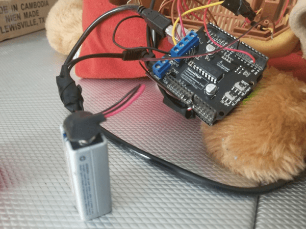
Motor Test Bench Talks The Torque

Salvaging a beefy motor is one life’s greatest pleasures for a hacker, but, when it comes to using it in a new project, the lack of specs and documentation can be frustrating. [The Post Apocalyptic Inventor] has a seemingly endless stockpile of scavenged motors, and decided to do something about the problem.

Once again applying his talent for junk revival, [TPAI] has spent the last year collecting, reverse-engineering and repairing equipment built in the 1970s, to produce a complete electric motor test setup. Parameters such as stall torque, speed under no load, peak power, and more can all easily be found by use of the restored test equipment. Key operating graphs that would normally only be available in a datasheet can also be produced.

The test setup comprises of a number of magnetic particle brakes, combined power supply and control units, a trio of colossal three-phase dummy loads, and a gorgeously vintage power-factor meter.

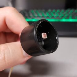
Motors are coupled via a piece of rubber to a magnetic particle brake. The rubber contains six magnets spaced around its edge, which, combined with a hall sensor,  are used to calculate the motor’s rotational speed. When power is applied to the coil inside the brake, the now magnetised internal powder causes friction between the rotor and the stator, proportional to the current through the coil. In addition to this, the brake can also measure the torque that’s being applied to the motor shaft, which allows the control units to regulate the brake either by speed or torque. An Arduino slurps data from these control units, allowing characteristics to be easily graphed.

If you’re looking for more dynamometer action, last year we featured this neatly designed unit – made by some Cornell students with an impressive level of documentation.

Continue reading “Motor Test Bench Talks The Torque”

Building A POV Display On A PC Fan

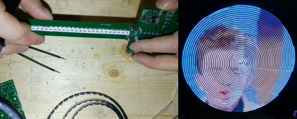
We’ve covered plenty of persistence of vision (POV) displays before, but this one from [Vadim] is rather fun: it’s built on top of a PC fan. He’s participating in a robot building competition soon and wanted to have a POV display. So, why not kill two birds with one stone and build the display onto a fan that could also be used for ventilation?

The display is a stand-alone module that includes a battery, Neopixels, Arduino and an NRF240L01 radio that receives the images to be displayed. That might seem like overkill, but putting the whole thing on a platform that rotates does get around the common issue of powering and sending signals to a rotating display: there is no need for slip connections.

[Vadim] goes into a good level of detail on how he built the display, including the problems he had diagnosing a faulty LED chip, and why it is important to test at each stage as it is easier to debug when the display isn’t whizzing around at high speed.

It’s a bit of a rough build that uses more protoboard than might be necessary, but we’re keeping our fingers crossed that it doesn’t fly off during the competition.

Continue reading “Building A POV Display On A PC Fan”

Arduino Revives Junkyard Laser Cutter

Some people have all the luck. [MakerMan] writes in to gloat tell us about a recent trip to the junkyard where he scored a rather serious looking laser cutter. This is no desktop-sized K40 we’re talking about here; it weighs in at just under 800 pounds (350 Kg), and took a crane to deliver the beast to his house. But his luck only took him so far, as closer inspection of the machine revealed it was missing nearly all of its internal components. Still, he had the frame, working motors, and laser optics, which is a lot more than we’ve ever found in the garbage.

After a whirlwind session with his wire cutters, [MakerMan] stripped away most of the existing wiring and the original control board inside the electronics bay. Replacing the original controller is an Arduino Nano running Grbl, likely giving this revived laser cutter better compatibility with popular open source tools than it had originally. Even though the laser cutter was missing a significant amount of hardware, he did luck out that both the motor drivers were still there (and working) as well as the dual power supplies to run everything.

After a successful motion test, [MakerMan] then goes on to install a new 90W laser tube. Supporting the tube is a rigged up water cooling system using a plastic jug and a cheap bilge pump. He also added an air assist system, complete with side mounted compressor. This pushes air over the laser aperture, helping to keep smoke and debris away from the beam. Finally, a blower was installed in the bottom of the machine with flexible ducting leading outside to vent out the smoke and fumes that are produced when the laser is in operation.

This machine is a considerable upgrade from the previous laser [MakerMan] built, and as impressive as this rebuild is so far, we’re interested in seeing where it goes from here. If you ask us, this thing is begging for an embedded LaserWeb server.

Continue reading “Arduino Revives Junkyard Laser Cutter”

PID Control With Arduino

Experience — or at least education — often makes a big difference to having a successful project. For example, if you didn’t think about it much, you might think it is simple to control the temperature of something that is heating. Just turn on the heater if it is cold and turn it off when you hit the right temperature, right? That is one approach — sometimes known as bang-bang — but you’ll find there a lot of issues with that approach. Best practice is to use a PID or Proportional/Integral/Derivative control. [Electronoob] has a good tutorial about how to pull this off with an Arduino. You can also see a video, below.

The demo uses a 3D printer hot end, a thermocouple, a MAX6675 that reads the thermocouple, and an Arduino. There’s also an LCD display and a FET to control the heater.

Continue reading “PID Control With Arduino”

Need A Thousand Extra PWM Pins?

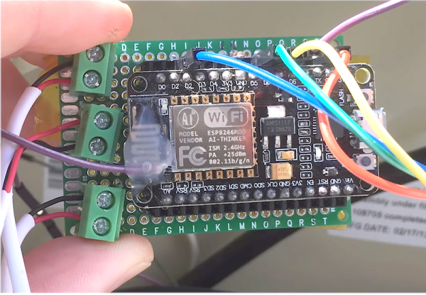
If your Arduino runs out of I/O lines, you can always add one of the several I/O expander chips that takes a serial interface to set its several pins. Or perhaps you could buy something like an Arduino Mega, with its extra sockets to fulfil your needs. But what would you do if you really needed more pins, say a thousand of them? Perhaps [Brian Lough] has the answer. OK, full disclosure: If you really need a thousand, the video isn’t exactly for you, as he shows you how to add up to 992 PWM outputs. The chip he uses works with any microcontroller (the video shows an ESP8266), and we suppose you could use two daisy chains of them and break the 1,000 barrier handily.

We like how short the video is (just two minutes; see below) as it gets right to the point. The PCA9685 chip gives you 16 12-bit PWM channels via an I2C interface. You can daisy chain up to 62 of the boards to get the 992 outputs promised.

Continue reading “Need A Thousand Extra PWM Pins?”

Art Deco Radio Gets FM Reception

Taking a vintage radio and cramming it full of modern, Internet-connected, guts has long been a staple of the hacking and making scene. While some might see it as a crime to take what’s arguably a legitimate piece of history and turn it into nothing more than a slipshod case for the Raspberry Pi, we have to admit there’s a certain appeal to the idea. Taking the beauty of classic design and pairing it with more modern capabilities is getting the best of both worlds.

But this project by [Nick Koumaris] is a somewhat unique take on the concept. Rather than sacrificing a real vintage piece of hardware to house the electronics, he’s designed a 3D printable case that looks like a classic 1936 AWA Radiolette. But what’s really interesting to us is that he then puts a basic FM radio inside of it.

That’s right, no Internet radio streaming or smartphone Bluetooth compatibility here. It’s just a regular FM radio, not entirely unlike the kind of hardware you’d expect to be inside of a classic radio. Of course, it’s much more modern, and [Nick] actually built it himself from a TEA5767 FM radio module and an Arduino Pro Mini.

While functionally it might not be terribly exciting, we do appreciate that he went through the trouble to make a vintage-looking user interface for the radio. While physical buttons would arguably have been more appropriate given the era, the art deco inspired font and graphics that show on the device’s Nokia 5110 LCD do look really slick.

Purists will surely be happy to see another project where a piece of vintage piece of audio equipment wasn’t sacrificed at the Altar of Hack, but we’ve also played host to many projects which weren’t nearly as concerned with historical preservation.

Continue reading “Art Deco Radio Gets FM Reception”

Handheld Arduino Light Painter

Light painting is a technique which allows you to “draw” on a photograph by moving a light past the camera during a long exposure shot. While it can be difficult to master, light painting allows for some incredible effects such as text and images that appear to be hovering in mid-air. Think of it like a very slow but much cooler version of an augmented reality app.

[Reven] recently wrote in to tell us about the Arduino light painter he put together, and while DIY (and even commercial) light painting gear isn’t exactly new at this point, we think he’s raised the bar a bit with his design. With the addition of a slick 3D printed enclosure and on-board display and menu system, his light painter looks exceptionally professional for being built out of hardware he had on hand.

On his blog, [Reven] has done a phenomenal job of documenting the build from start to finish. Not only does he include a detailed Bill of Materials and the STL files so you can build your own version of his light painter, he walks the reader though his design process and explains why he did the things he did. Even if you aren’t interested in building a light painter, there’s almost certainly something of interest for anyone who’s ever looked at a pile of parts on their workbench and wondered how they were going to turn it into a functioning device.

Powered by an Arduino Uno, the light painter provides a user interface on a 16×2 LCD which allows control over not only the brightness of the WS2812 LED strips but selecting and loading different images from the micro SD card. The case was designed in FreeCAD, and while [Reven] mentions there are a number of issues which could be improved, satisfies all his design goals.

We covered the original Adafruit project that [Reven] based his code all the way back in 2013, though there’s certainly been more modern interpretations of the idea since then.