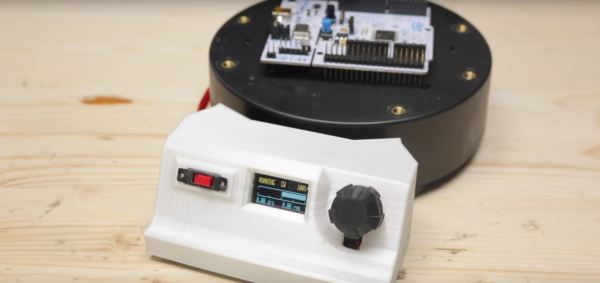
[Robin Reiter] needed a better way to show off his work. He previously converted an electric TV stand into a full 360-degree display turntable, but it relied on an external power supply to get it spinning. It was time to give it an upgrade.
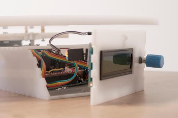
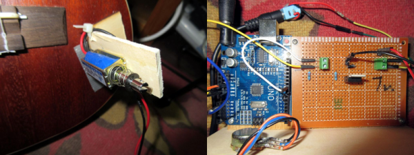
Putting his spacial organization skills to work, [Reiter] has crammed a mini OLED display, rotary encoder, a LiPo 18650 battery and charging circuit, a pair of buck converters, a power switch, and an Arduino pro mini into the small control console. To further maximize space, [Reiter] stripped out the pin headers and wired the components together directly. It attaches to the turntable in question with magnets, so it can be removed out of frame, or for displaying larger objects!
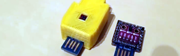
When first powered on, the turntable holds in pause mode giving [Reiter] time to adjust the speed and direction. He also took the time to add an optical rotary encoder disk to the turntable and give the gearing a much needed cleaning. Check out the project video after the break!
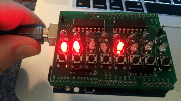
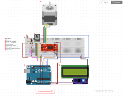
 [Allan] starts with a basic breadboard design, draws a schematic, prototypes the circuit, then designs the PCB and orders it online, followed by assembly and testing. [Allan] had previously taught himself to use